SIPLACE Vision Customer_en.pdf - 第50页
Component Shapes Specific Component Shapes BareDie Component Shape S tudent Guide SIPLACE V ision (Customer) Component Shapes Edition 12/2008 EN 50 5.3.2 BareDie Component Shape JEDEC description JEDEC description Sinc…

Component Shapes
Unleaded Component Shapes Specific Component Shapes
Student Guide SIPLACE Vision (Customer)
Edition 12/2008 EN Component Shapes
49
5.3 Specific Component Shapes
The following pages describe the key component shapes with programming information for SIPLACE
Vision.
The last item in each case, dataset, refers to the SIPLACE Pro option in which datasets for SIPLACE
Vision and the older ICOS Vision systems can be managed separately. The Requires separate group
description checkbox creates separate folders for these datasets. Only enable this checkbox if you are
unable to assign separate descriptions to these datasets. Using this option too often will increase your
data management work.
5.3.1 Unleaded Component Shapes
Definition
Components, which have no leads or which have leads situated inside the body dimensions, will be
specified as unleaded shapes in this section.
In these cases, SIPLACE Vision will not perform lead measurement (exception: extensions 702 SW).
From SC/MC 702 (SV 4.0.1) (see: New SV functions 702), BareDie and molded components can
also be used for face down recognition (non-specific component features), in addition to the CHIP
components.
CHIP and molded CSs have an additional lead length inspection.
Measurement procedure
The component position and angle at the nozzle are determined through gradient formation and various
other steps. In a second step, the body dimensions are determined through gradient formation and other
measurement steps.

Component Shapes
Specific Component Shapes BareDie Component Shape
Student Guide SIPLACE Vision (Customer)
Component Shapes Edition 12/2008 EN
50
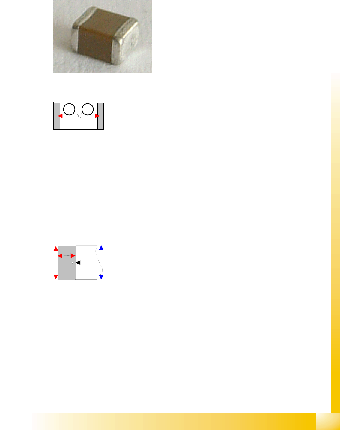
5.3.2 BareDie Component Shape
JEDEC description
JEDEC description
Since there are no leads on the underside of the component, a group description is not required.
Lead description
There are no leads which need to be recognized.
The measurement method used is Body Dimension Check (no multiple measurement possible).
Special features
BareDies are component shapes which are connected or bonded (i.e. with gold wire) from the top
side.
BareDies must be symmetrical. In contrast to the ICOS system, SIPLACE Vision does inspect this
optically visible symmetry.
Since the component needs to be centered with the help of body dimension measurement,
inspection mode is set as a default.
The back surface is highly reflective. It needs to be illuminated with an illumination angle of 0°, to
ensure that this mirror reflects correctly.
MFU ceramic components are a special type of BareDies.
The illumination of the BareDie defaults needs to be changed from steep to flat for these
components.
Joint datasets with ICOS data possible:There are no fundamental differences during evaluation.
Due to the very simple programming method, ONLY involving body size, NO component shape wizard
is offered for BareDie programming.
SW extensions: FaceDown recognition (See: New Siplace Vision Functions 702).can be programmed
and from SC 702.01 SW (SIPLACE Vision 4.1).
Body description: rectangular.
The Z height of the body determines the measurable height
in the CO sensors.
The X/Y body dimensions determine the field of vision, the
Region of Interest.
Component Shapes
CHIP Component Shape Specific Component Shapes
Student Guide SIPLACE Vision (Customer)
Edition 12/2008 EN Component Shapes
51
5.3.3 CHIP Component Shape
JEDEC description
JEDEC description
Lead description
Body description: rectangular.
The Z height of the body determines the measurable height
in the CO sensors.
The X/Y body dimensions determine the field of vision, the
Region of Interest.
This also determines the outer starting edge of the
Wraparound leads.
This component consists of two lead groups, each with one
lead.
The leads in the two groups must be identical! This
restriction no longer applies with SC 702 (although you do
need to switch over to "separate group descriptions" for
ICOS –SIPLACE Vision).
The leads are inside the body surface.
In the case of this component, the leads are understood to
begin where the body begins, meaning that a group offset
does not need to be programmed.
After optical centering, the distance between the leads and
the center (body center) is measured and used for the
placement coordinates.
Left: pin begins here
Right : pin ends here*
Vertical red arrow: lead width
This component shape has so-called Wraparound leads,
which are wrapped around the component body, hence the
name Wraparound.
This defines the default lead direction: towards the CO
center (correct for Tantals (Moulded), reprogram if
necessary);
The lead description also includes the lead length and
width.
The leads are as wide as the overall body (if the leads are
narrower than the body, the CO is classified as Moulded).
The lead length must not exceed 50 percent of the body
length
No notches may be programmed.
*The pin end is shown by a point in the results diagram.
1 2