SIPLACE Vision Customer_en.pdf - 第89页
Component Shapes Optical Recognition of Hemispherica l Leads Specific Component Shapes S tudent Guide SIPLACE Vision (Customer) Edition 12/2008 EN Component Shapes 89 5.3.10 Optical Recognition of Hemispherical Leads The…
Component Shapes
Specific Component Shapes Components With Round Leads
Student Guide SIPLACE Vision (Customer)
Component Shapes Edition 12/2008 EN
88
Note: A small pitch tolerance and diameter tolerance must guarantee that the PCB drilling is accurately
touched. Support the PCB area for this TH placement well so that the PCB is not bent, leading to
additional insertion errors with the pins.
Types
Key points for placement – Z-axis dynamics downwards – :
If pins or contacts or inserted through the board holes, make sure that the placement force is
programmed sufficiently high.
You will also need to set a low travel speed. Select a travel profile with Slow braking (profile 6 or 8).
This currently means that the axis travels the last ~1 mm (before reaching the placement height) at
its slowest speed.
If the board holes are large enough to make increased force unnecessary (example 1), you can use
the timesaving standard travel profile.
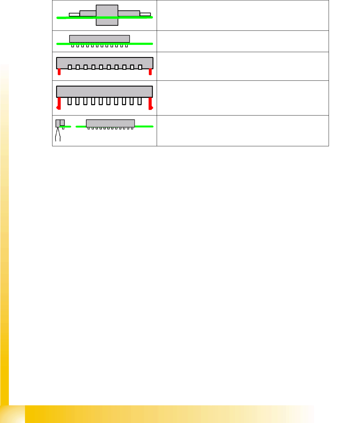
Components on which the parts protrude through the PCB cutouts
Components on which the electrical contacts protrude through the
board.
Components with additional centering pins.
Components with locking pins; these require a significantly higher
placement force (see Options).
Connectors aligned away from the board or related combinations.
Appropriate PCB supports are required under the nozzle contact point.
Component Shapes
Optical Recognition of Hemispherical Leads Specific Component Shapes
Student Guide SIPLACE Vision (Customer)
Edition 12/2008 EN Component Shapes
89
5.3.10 Optical Recognition of Hemispherical Leads
The BGA centering procedure determines the CO center position, based on the data from ball
recognition with
A.) Pre-centering and
B.) Component inspection of ball lead.
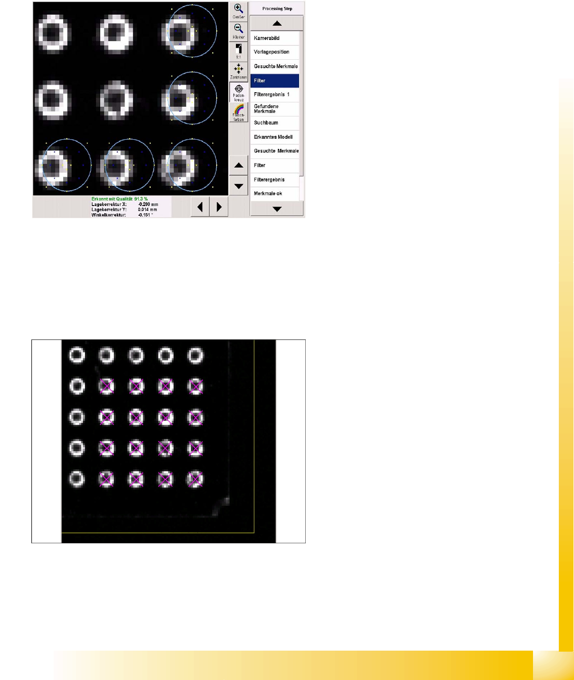
Filter for pre-centering at the CO corners
Five ball leads are searched for in each CO
corner. These 20 features facilitate fast and
accurate determination of the CO position.
Template filter in the bottom right CO corner.
The light blue ring shows the programmed ball
diameter.
The typical representation of a ball is the ring-
shaped reflection from flat illumination.
The required filters show two dark areas.
The yellows points on the outside show the CO
body.
The blue points show the reflecting sides of the
ball lead.
The yellow points on the inside show the flat
part of the ball lead.
Do not enable steep illumination for hemispherical
leads, since the missing balls will not be
recognized in this case i.e. metallic lead surfaces
without balls would be displayed identically.
Ball leads in the corner region
Component Shapes
Specific Component Shapes Optical Recognition of Hemispherical Leads
Student Guide SIPLACE Vision (Customer)
Component Shapes Edition 12/2008 EN
90
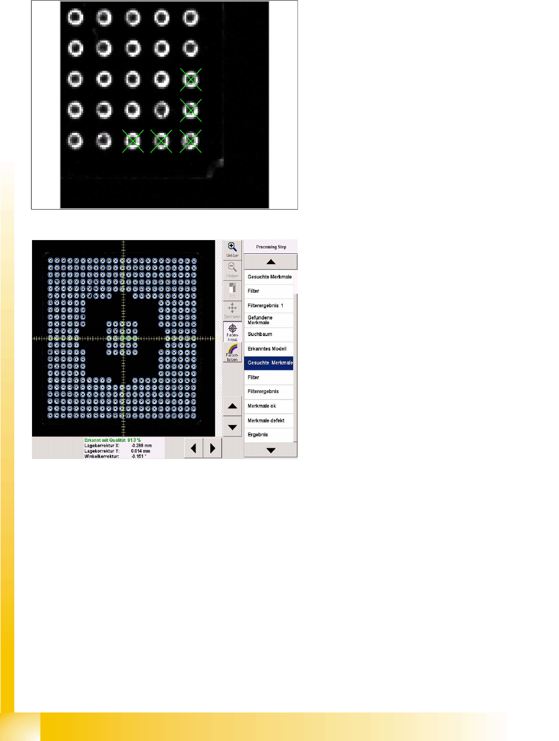
Component inspection process Features
searched for
All balls enabled during programming will be
inspected with the above mentioned filter.
If a particular ball does not achieve the required
quality, this will be shown in the Feature faulty
menu.
Filter 22 is used to process CCGA components.
This filter does not have the central, dark point.
Circles in Shield programming are processed with
filter 32.