SIPLACE Vision Customer_en.pdf - 第26页
User Interface Menu for Results and Recognition Steps Stati on Interface for Teaching Component Shapes S tudent Guide SIPLACE V ision (Customer) User Interface Edition 12/2008 EN 26 4.5 Menu for Result s and Recognition …
User Interface
Station Interface for Teaching Component Shapes Editing the Camera Image (for all Vision Menus)
Student Guide SIPLACE Vision (Customer)
Edition 12/2008 EN User Interface
25
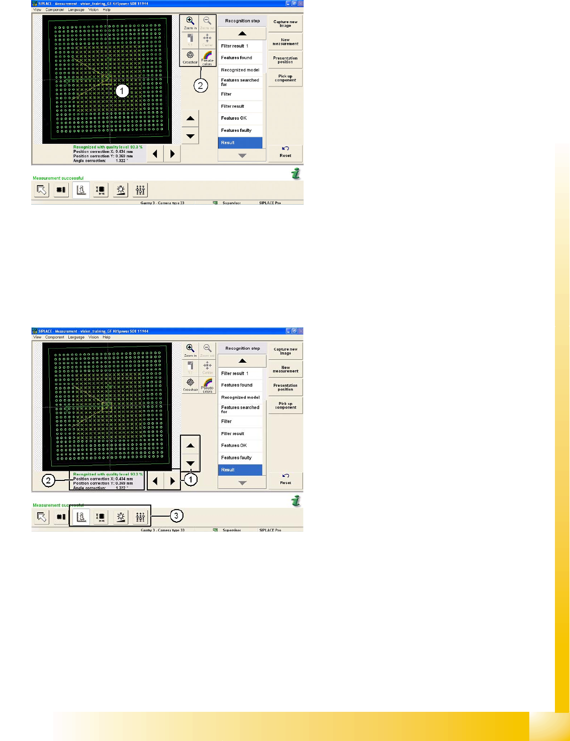
Editing the camera image
Legend
The digital camera image can be made larger (up
to the display of individual pixels) and smaller with
the zoom function.
1. Camera image of component (camera center)
2. Camera tools menu with the following buttons:
Zoom in
zooms in on the component image
step by step, starting from the component
center. The same happens when the user
touches any part of the camera image.
Zoom out
reduces the size of the camera
image again, step by step.
1:1 resets the image to its original size and
aligns it in the center of the image area.
Center
centers the component image section.
Crosshairs
shows camera crosshairs in the
image for position and size assessment.
Pseudo colors
This helps you evaluate the
contrast of specific features.
Legend
1. Use the arrow keys to move the section of the
camera image.
2. This shows the centering result/error or the
evaluation, consisting of position correction
data (X, Y and Z values) and the angle
correction value.
3. Further Vision menus include
Result
,
Geometry
,
Illumination
and
Algorithms
.
User Interface
Menu for Results and Recognition Steps Station Interface for Teaching Component Shapes
Student Guide SIPLACE Vision (Customer)
User Interface Edition 12/2008 EN
26
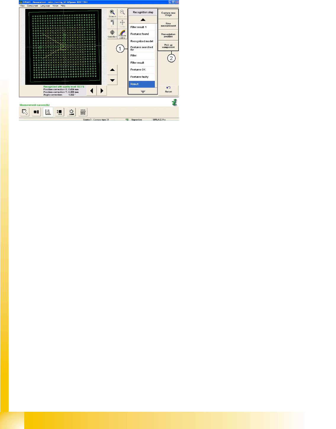
4.5 Menu for Results and Recognition Steps
1. Individual step selection for centering of
component type.
Recognition step selection: each individual
centering step for a particular CS type can be
selected for (error) analysis purposes.
2. Camera menus:
– Capture new image: The camera
illuminates the component and records a
new image.
– New measurement : A new analysis is
performed with the stored data from the
last image recording.
– Presentation position: This shows the
expected component position.
– Pick up component: This rejects the
current component, fetches a new one
from the feeder and places it in front of the
camera.
User Interface
Station Interface for Teaching Component Shapes Checking and Correcting the Geometry.
Student Guide SIPLACE Vision (Customer)
Edition 12/2008 EN User Interface
27
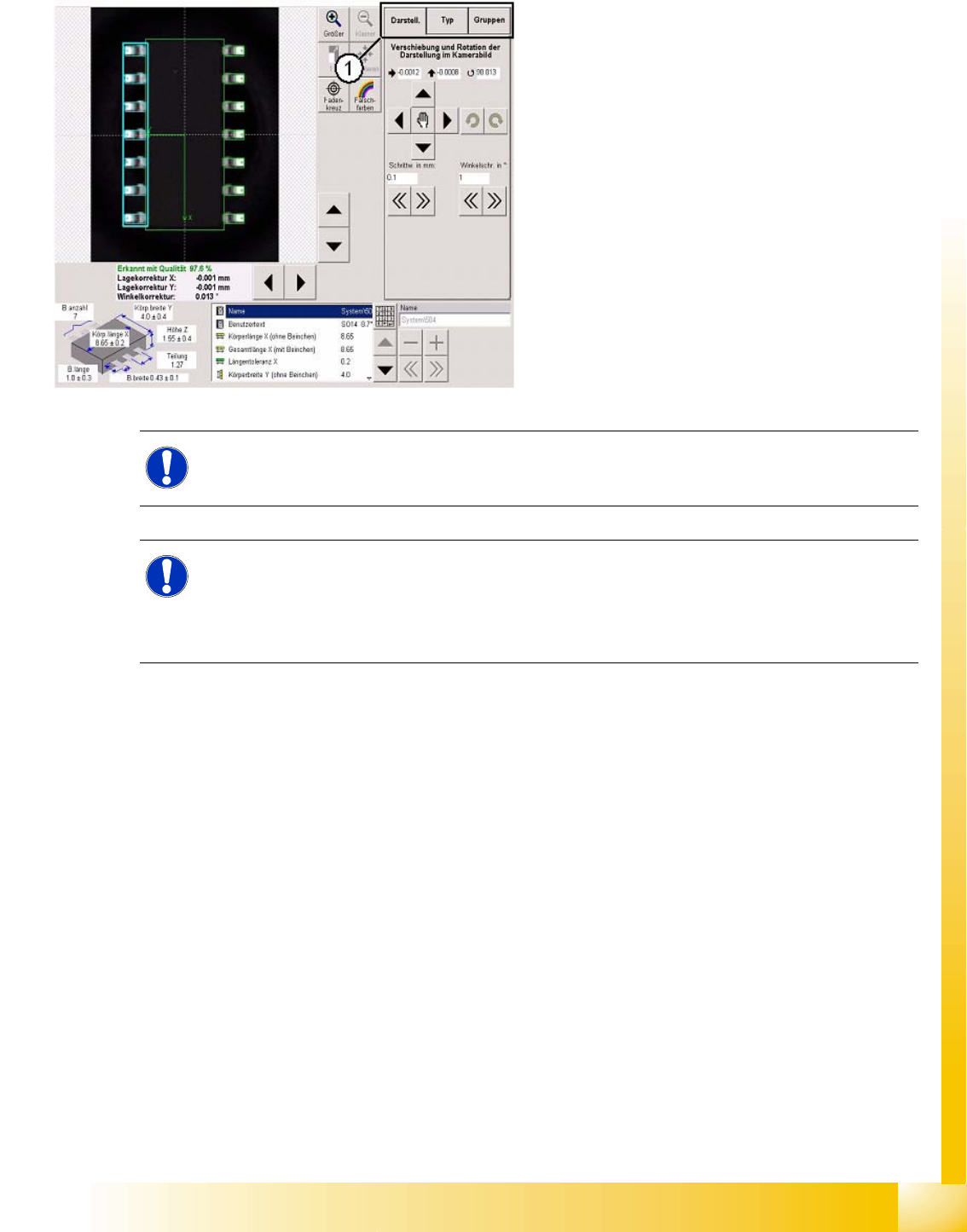
4.6 Checking and Correcting the Geometry.
1. The following settings can be defined in the
three tabs provided:
– Use the menu View to set the green,
programmed CS outline on top of the
camera image.
– Use the Type tab to reassign the SIPLACE
Vision CS type.
Make sure that the programming
corresponds to the newly selected CS
type, otherwise the system will overwrite
your CS data with standard settings!
– Use the menu Groups to reprogram the
lead group and the lead itself.
NOTE:
The above diagram shows an angle of 90 degrees.
NOTE: Changes affect the optical recognition in ICOS camera systems
If a common CS description has been selected for this component in SIPLACE Pro, the settings
will also influence the optical recognition by the ICOS camera systems.
X You may need to select Requires separate group description in SIPLACE Pro. After this,
reteach the component shape.