SIPLACE Vision Customer_en.pdf - 第135页
SIPLACE Vision - T eaching Fiducials Synthetic Fiducials for Position Rec ognition Applications Fiducial shapes S tudent Guide SIPLACE Vision (Customer) Edition 12/2008 EN SIPLACE Vision - T eaching Fiducials 135 6.2.1.3…

SIPLACE Vision - Teaching Fiducials
Fiducial shapes Synthetic Fiducials for Position Recognition Applications
Student Guide SIPLACE Vision (Customer)
SIPLACE Vision - Teaching Fiducials Edition 12/2008 EN
134
6.2.1.2 Shapes and Sizes of Synthetic Fiducials
The cross is the most suitable fiducial shape, as the ends of the cross bars can be cut off and the
fiducial reference point still remains in the center of the cross. This shape does not require much
space on the PCB layout.
SIPLACE Vision detects the doublecross as a geometric shape by searching for all outer and inner
edges. There is therefore only one fiducial reference point, in the center of the fiducial. (In ICOS
brightness evaluations, doublecrosses with unfavorably long outer arms could cause the
coincidental and faulty detection of 4 "auxiliary positions" as the correct fiducial center.)
Squares, as a special type of rectangle with even sides, are not listed as a separate programming
item. A rectangular, square ring is a fiducial shape which hardly ever appears on a standard PCB
layout.
A square rotated by 45° is known as a diamond and is classified as a filled synthetic fiducial.
The circle and the circular ring are frequently used fiducial options. When selecting the circular ring,
which uses the "vias" of multiple PCBs, make sure you pay attention to the quality of the outer line
of the metallic ring. If this outer line is not totally circular for all PCBs, we advise using dark circles
on a bright background, unless other suitable fiducials are available in the PCB layout.
All other shapes can be trained as samples (explanations in following text).
Geometric
fiducial shape
Min. structure size Max. structure size Min. tolerance Max. tolerance
Circle Diameter: 250 µm Diameter: 3 mm 2% of nominal
dimensions
20% of nominal
dimensions
Cross Size: 300 µm
Bar width: 100 µm
Size: 3 mm
Bar width: 1.5 mm
2% of nominal
dimensions
20 % of nominal bar
width, from SC/MC
702 30%
Doublecross Size: 500 µm
Bar width: 100 µm
Extension:100 μm
Size: 3 mm
Bar width: 1.2 mm
2% of nominal
dimensions
20 % of nominal bar
width, from SC/MC
702 30%
Rectangle/
square
Length: 250 µm
Width: 250 µm
Length: 3 mm
Width: 3 mm
2% of nominal
dimensions
20% of nominal
dimensions
Rectangle/
square frame
Length: 300 µm
Width: 300 µm
Frame thickness: 100 µm
Length: 3 mm
Width: 3 mm
2% of nominal
dimensions
20% of nominal
dimensions
Circular ring Diameter: 300 µm
Ring thickness:100 µm
Diameter: 3 mm 2% of nominal
dimensions
20% of nominal
dimensions
Diamond Length/width: 350 µm Length/width: 3 mm 2% of nominal
dimensions
20% of nominal
dimensions
Pattern Length/width: 500 µm Length/width: 3 mm 2% of nominal
dimensions
20% of nominal
dimensions
SIPLACE Vision - Teaching Fiducials
Synthetic Fiducials for Position Recognition Applications Fiducial shapes
Student Guide SIPLACE Vision (Customer)
Edition 12/2008 EN SIPLACE Vision - Teaching Fiducials
135
6.2.1.3 Recognition of Synthetic Fiducials
One of the 3 position recognition fiducials should have at least the maximum position correction
(otherwise the error
ROI (Region of Interest) too small
will be issued).
The other two fiducials can have limited presentation tolerances:
max. position correction = (FOV – fiducial size inc. size tolerance) / 2
e.g. X = (5.7 mm – 2.1 mm) / 2 = 1.8 mm
During placement, the position fiducials are approached in the order of their search field size.
If the position correction of the fiducial has been restricted in SIPLACE Pro, this value will be shown as
the correction value in the "Position correction X/Y" lines.
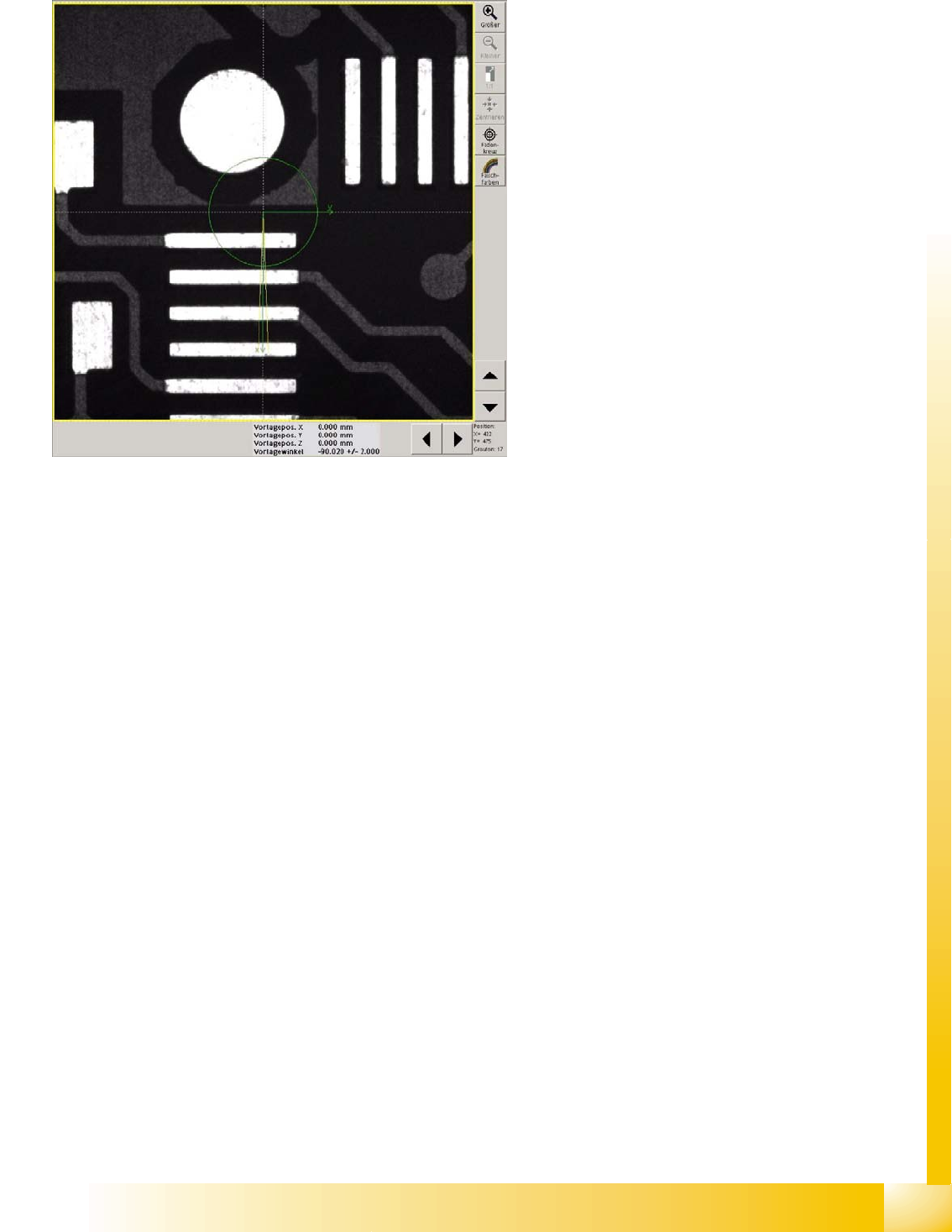
6-5: Position correction
The centering step camera image shows the
unedited camera image resulting from the current
PCB position and PCB camera at the theoretical
fiducial position in the machine.
The centering step "position correction" shows the
fiducial shape and size in the PCB camera center,
with the permitted angle correction of 2°.
The angle shows the assembly position of the
camera at the gantry and the PCB camera
calibration angle.
If a position correction is programmed which
corresponds to the whole PCB camera field of
vision (5.7x5.7mm), the yellow frame of the search
field will show the relevant extract from the whole
image.
When the position correction is the same as the
whole camera field of vision, no X/Y position
correction will be shown in the results line.
SIPLACE Vision - Teaching Fiducials
Fiducial shapes Synthetic Fiducials for Position Recognition Applications
Student Guide SIPLACE Vision (Customer)
SIPLACE Vision - Teaching Fiducials Edition 12/2008 EN
136
75% (standard) of the point pairs (edge search positions) need to be recognized, so that the fiducial
measurement results are shown at the bottom (middle) of the image (see also algorithm settings).
The tolerance values for the bar width (max. 20%) alter the point pair pitch for the precentering of the
cross fiducial and therefore also affect the marking lines for the fine edge search.
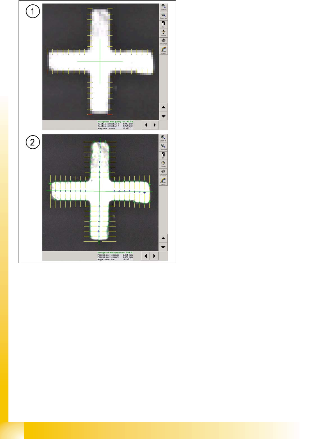
6-6: Fiducial centering steps with standard algorithm settings
Legend
1. Subsampling shows the 16 (standard in
algorithm setting) point pairs of the cross bars.
One of the pixels (marked blue) in the pair
must reach the bright fiducial foreground and
one (yellow) must reach the dark background,
before the point pair connection is marked
yellow and can be used for precentering the
fiducial position. Positions which are marked
red will be rejected.
2. The Fine search examines the brightness
transitions along the lines connecting the 16
point pairs, determined in the rough search, to
determine the exact fiducial center point. The
green crosses mark the position of greatest
gradient change. The blue dot marks this
position if the distance is within the bar width
tolerance range (fine structure).
The fiducial edge positions are calculated and
used to accurately interpolate the fiducial
center.