SIPLACE Vision Customer_en.pdf - 第198页
List of selected nozzle types recognized for mechanicall y f itting to the component s urface, height and weight . This list is to program ’Reduced Acceleration’ for any ma chine axis if proc essing the component show an…
linienfarbe 192,26,128
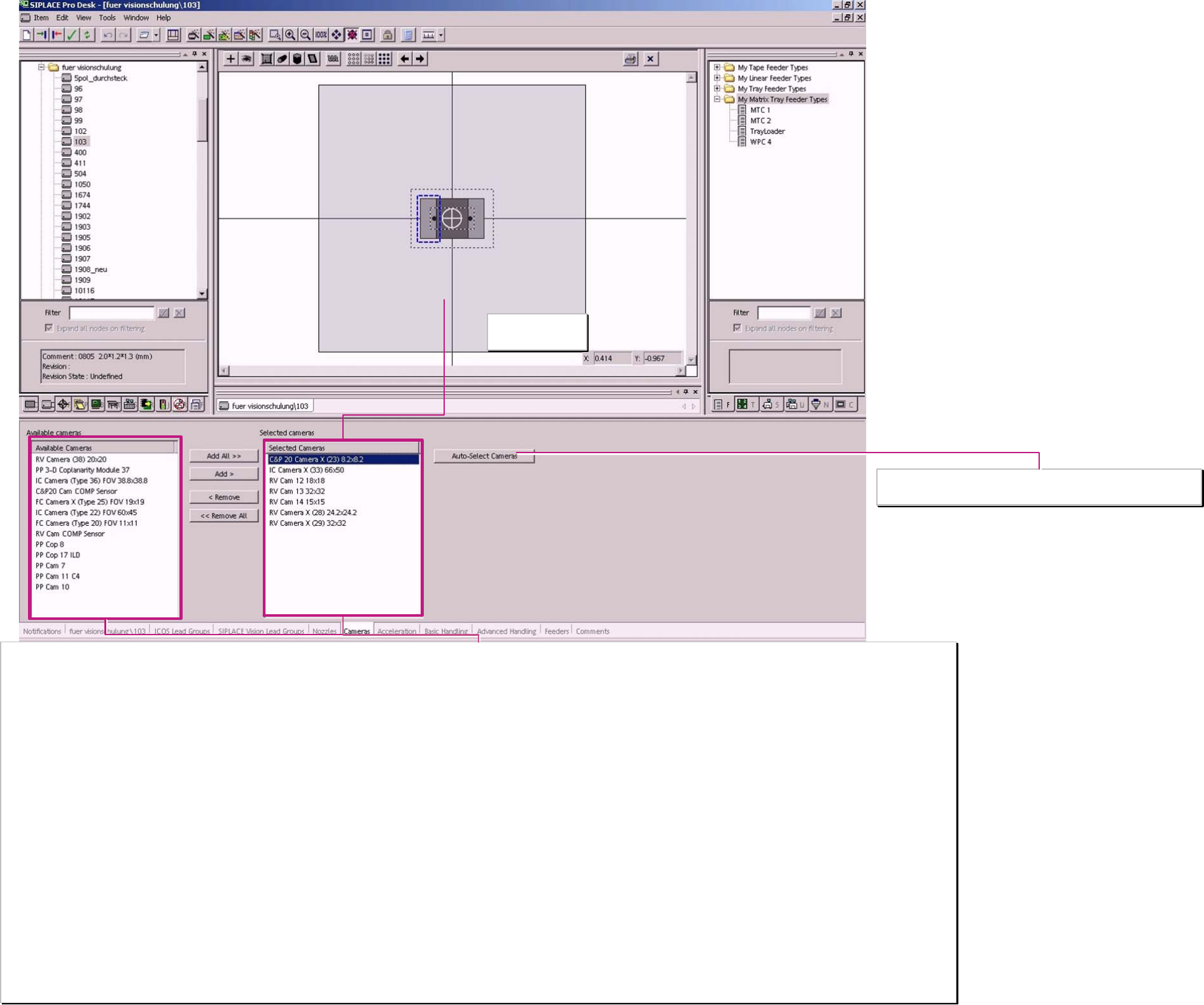
Camera selection list
From this list choose the automatic camera selection. The list is updated when new Station SW introduces new Camera systems.
Sensors which are NOT a Camera:
PP Cop 8 LDM- Coplanarity module at F3 machines
PP Cop 17 ILD Coplanarity module for F5 HM / HF / X and D. Scanning with a punctual LASER for Gullwings.
PP 3-D Coplanarity module 37 For X-machines with TWIN-head. 3D coplanarity module for gullwing comp. and BGA’s scanning with a line shaped LASER.
RV Cam Comp sensor the comp. sensor for the C&P12 head. With shadowing method for comp. up to ~4,5mm comp. height and with nozzles longer 12,5 mm (901…907 … 915)
C&P20 Cam Comp sensor is the comp. sensor always necessary for comp. recognition at C&P20 head.
Cameras
The naming of the camera names contain the field of view (FOV) or the maximum component size.
FoV for SIPLACE Vision Cameras:
RV Camera 38 (20x20) (0402mm (01005) camera for C&P12 04x02mm ->16x16mm)
RV Camera X (28) 24,2x24,2 Standard camera for C&P12-head 10x05mm up to 18,7x18,7 (PLCC44)
RV Camera X (29) 32x32 Standard camera for C&P 6 06x03mm (0201) up to 27x27mm or for ’HR option on C&P12 head
IC Camera (Type 36) 38,8x38,8 refer to the parameter of the PP Cam 10 used at SIPLACE Vision at the D1-series machine 32x32mm max. comp size for single measurement
IC Camera X (33) 66x50 Comp. Camera for X/D3 with TWIN & as an option for D1 55x45mm comp. Size for single measurement
FC Camera X (TYPE 25) FOV 19x19 for FlipChip placement with Twin on X or D-machines 16x16 mm comp. Size for single measurement
C&P 20 Camera X (23) 8,2x8,2 This is the only camera for C&P 20 and allows placement for 0402mm (01005) up to 6x6mm (2220 / SO6 / SO8) with tiny comp. - and pickup tolerances.
FoV for ICOS Cameras:
IC Camera (Type 22) FOV 60x45 Comp. camera for HF with TWIN 50x40mm comp. Size for single measurement
FC Camera (type 20) FOV 11x11 FlipChip Camera option for HF-machines 8x8mm comp. size for single measurement
Max. comp. size for ICOS Cameras:
RV Camera 12 18x18 comp. camera for C&P12 10x05mm up to PLCC44
RV Camera 13 32x32 for C&P6-head comp. size like for PP Camera 7/10 in single measurement 38x38mm FoV
RV Camera 14 15x15 for HR- and BareDie-Option on C&P12 head so called BareDie Camera. 13x13mm comp. size
PP Cam 7 38x38mm (FoV) first stationary IC-head camera at F3 32 x32mm comp. size for single measurement.
PP Cam 10 38x38mm (FoV) newer IC-Camera for IC-heads at F5HM 32 x32mm comp. size for single measurement & with BareDie illumination up to 15x15mm comp. size
PP Cam 11 C4 12x9mm (FoV) FlipChip-Camera option for Fx-machine types 7x7mm comp. size for single measurement
Field of View (FoV)
of selected camera
Component shape cameras
and sensors
From the camera selection list left select the ...
… automatical selection of camera
A programing overview about process reliability Editon for SIPLACE Pro 5.0 extended for 5.2
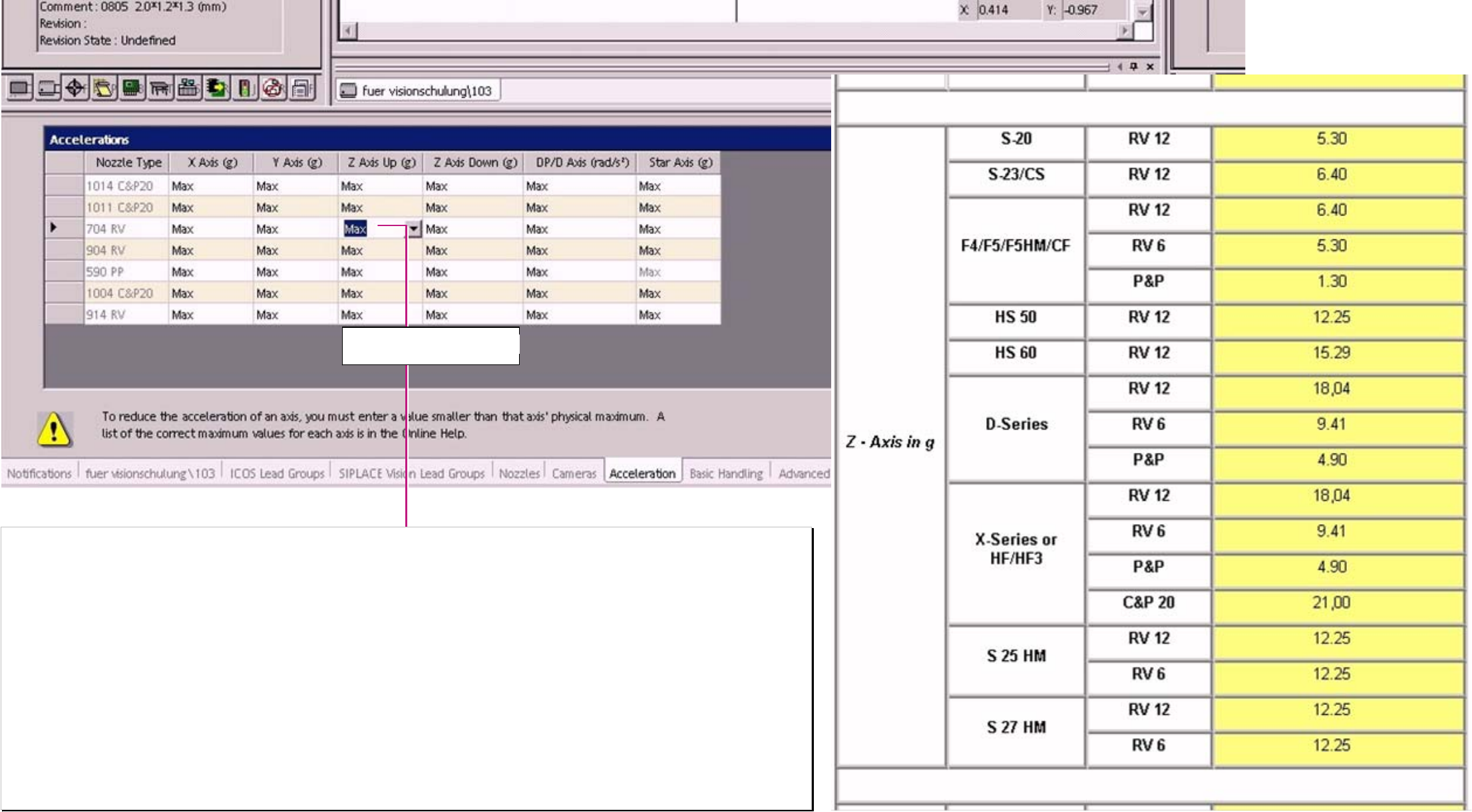
List of selected nozzle types recognized for mechanically fitting to the component surface, height and weight.
This list is to program ’Reduced Acceleration’ for any machine axis if processing the component show any weakness.
In this list an axis specific reduced acceleration could be programmed for the placement sequence with a desired nozzle type This influence the force to the contact area
comp.- nozzle (the lower accel. The lower required holding force for the component).
Overwrite the “Max“ text with the desired value!
In the Online help (F1) you find a list with all machine types and with the max. acceleration of the respective axis type. There you could see to which acceleration you have
to reduce to get an effect on the axis of your actual machine type.
Error situation:
comp. remain in the tape / feeder no solution with reduced acceleration – the comp. Could not be picked. –examine the pickup area fort the reason.
The special dynamic profile start Z-Axis slowly upwards- might be a better solution.
comp. drop back to the feeder Z-acceleration for upward movement is too high for q comp. with bad nozzle contact.
comp. placed twisted the comp. was turned after the optical recognition; improvement (correct nozzle 93X) otherwise reduced acceleration for
DP and Star axis.
comp. twisted below the camera the comp. was turned before the optical recognition; improvement (correct nozzle 93X) otherwise reduced acceleration for
DP and Star axis.
comp. placed shifted rubber nozzle 93X or 518/519 or reduced acceleration X/Y-axes.
Component shape
reduced acceleration
‚Z DOWN’ mean Z DOWNwards
‚ Z UP’ mean Z UPwards
A programing overview about process reliability Editon for SIPLACE Pro 5.0 extended for 5.2
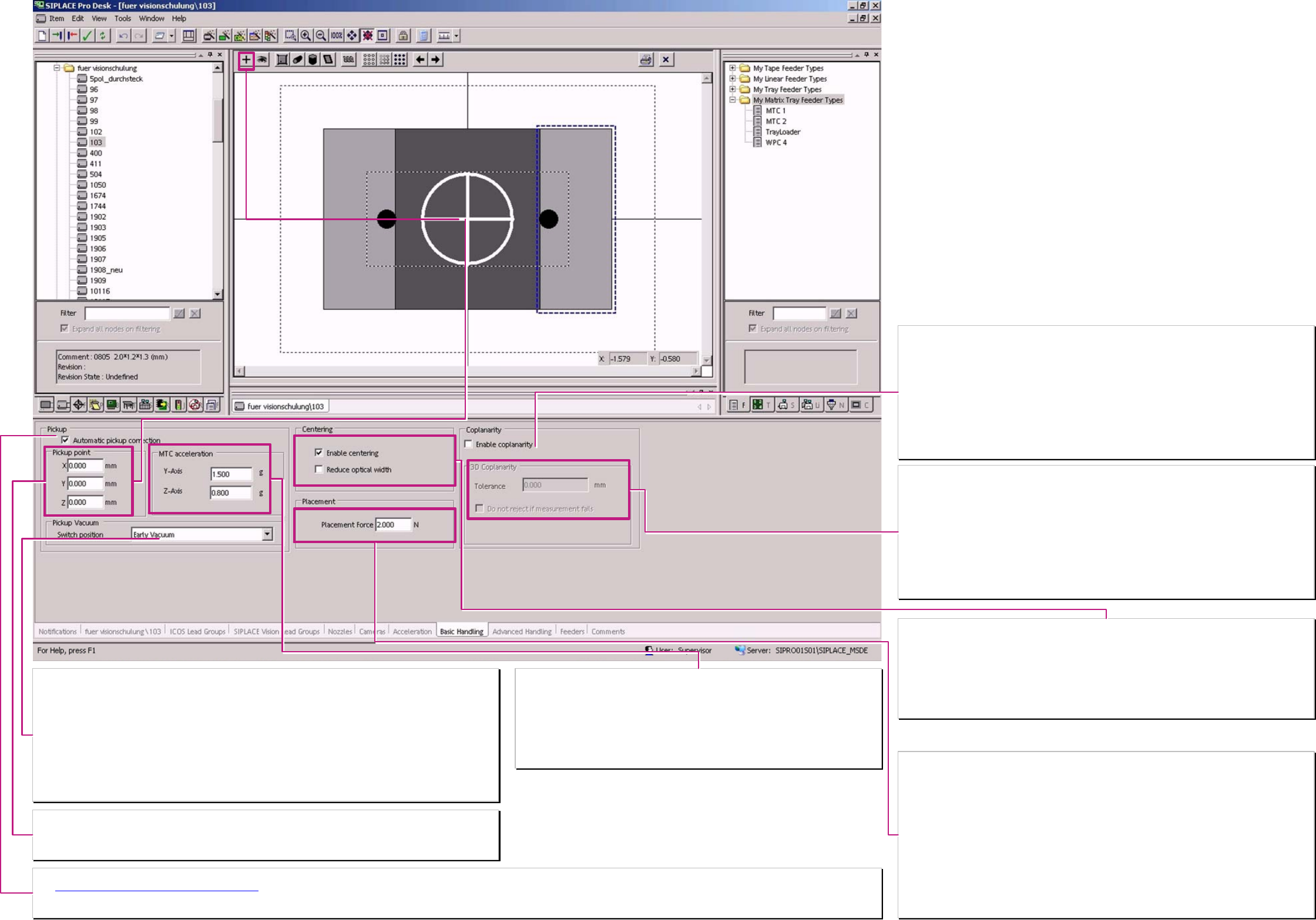
Switch position (the trigger time for vacuum).
Here is defined the operation mode for triggering vacuum on placement heads. (nicht für SC/MC SW 4xx)
Normal vacuum:
at the placement heads the vacuum is activated when the nozzle contacts the component in the feeder.
TWIN, always and at C&P12 / 6 head for nozzles with components bigger 6x6x4mm
Early vacuum:
The vacuum is activated at at C&P12/6 when the LB top is triggered at downward movement for pickup
(at 901/911/925.. already at start downward)..
C&P20-head operates always with early vacuum (at start downward for all comp.smaller than 6x6x4mm)
TWIN-head – never operates with early vacuum.
(Do not mix up with early air kiss in Nozzle programming (valid since SC/MC 604.xx & A364 axis controller))
Nozzle pickup point on component shapes
Here is the contact position⊕ of the nozzle at the component shape to change. This function is not valid for all
versions of station-SW.
Normal nozzle pickup point is identical with the comp. shape reference pos. (comp. shape center)
Acceleration values MTC/WPC4 axes.
Normal acceleration/deceleration
The standard value is for the fastest operation of the machine.
So here is only the possibility to reduce the values:
The acceleration/deceleration value of the Y-axis is valid for the comp. shape –
mean for the respective Level / Tray.
The Value for Z-axis is valid for the respective Tower with the component (MTC).
Automatical Pickup correction
The Pickup position correction for X/Y-pickup position
could be disabled here for exotic components.
The correction is calculated from the position result of the optical centering of the component & the calibration data of the segment. For Melf comp. shape types this function is ‘automatically’ deactivated.
Z-pickup height correction is NOT to disable. (The placement height learning and correction is also not to disable.)
Placement force
The programmed value here is become active ONLY when the respective dynamic profile is
selected in ‚Advanced handling. (The dynamic profile have to be programmed for SC/MC SW 502
and onwards.)
C&P 20 2 N Standard up to 4.5N
C&P 6/12 2 N Standard up to 5 N
TWIN 2 N Standard 1 up to 15N
TWIN-high force 2 N Standard 1 up to 30N
Is for the TWIN (P&P) in ‚Advanced handling’ (see advanced hand. II) a waiting time bottom for
placement combined with this increased placement force so the servo might trigger an ‘over
current error’ (error message I
RMS
). This depend on the thermic stress state of the servo and the
programmed waiting time of 2,5 sec respectively more for increased placement force.
At High Force option the Servo amplifier trigger characteristic is adopted to the motor thermic
characteristic that in normal operation area up to 15 N no error is triggered.
Centering
’Centering’ has to be always active!!!
Only than the component is optically recognized and correct placed.
For internal tests this could be deactivated (all the component cameras are inactive).
Reduced optical width
is only necessary for the Re-export to Unix/Linux LC!
The reduced optical width for the MELF’s is taken from the body shape programming ‚Horizontal
cylinder’.
❑ Enable Coplanarity check
components base on this component shape could be measured with Coplanarity module(Do not
forget to program the sensor).
F- / HF-/ D- machines
have the coplanarity module ILD 2000 / 2200. This module scan with a punctual laser the Gullwing
pins of SO/ QFP/BQFP.
X-machines
may have installed as an option a 3D- coplanarity module. Here scan a laser line the SO/QFP/
BQFP OR ALSO a BGA.
3 D – Coplanarity module
This Option is ONLY to install on an X3 with Box-PC for gantry 3 with TWIN-head.
Tolerance
This tolerance here is the comp. shape-specific tolerance of the balls from a BGA – this terminals
could collapse during soldering process.
This mean;
for a BGA is a component shape specific larger tolerance possible than programmed for the
solder paste thickness in the PCB programming for the QFP/ … comp. shapes.
❑ Do not reject if measurement fails
This setting allows a repeated measurement on the coplanarity module with using the height
measurement results of the measurement for height adjustment.
Component shape
basic handling
A programing overview about process reliability Editon for SIPLACE Pro 5.0 extended for 5.2