SIPLACE Vision Customer_en.pdf - 第101页
Component Shapes SIPLACE Vision Image Export/Import New SIPLACE Vision Functions for 605 and 701 Statio n SW S tudent Guide SIPLACE Vision (Customer) Edition 12/2008 EN Component Shapes 101 5.4 New SIPLACE Vision Functio…
Component Shapes
Specific Component Shapes Optical Recognition of Free Programmed COs
Student Guide SIPLACE Vision (Customer)
Component Shapes Edition 12/2008 EN
100
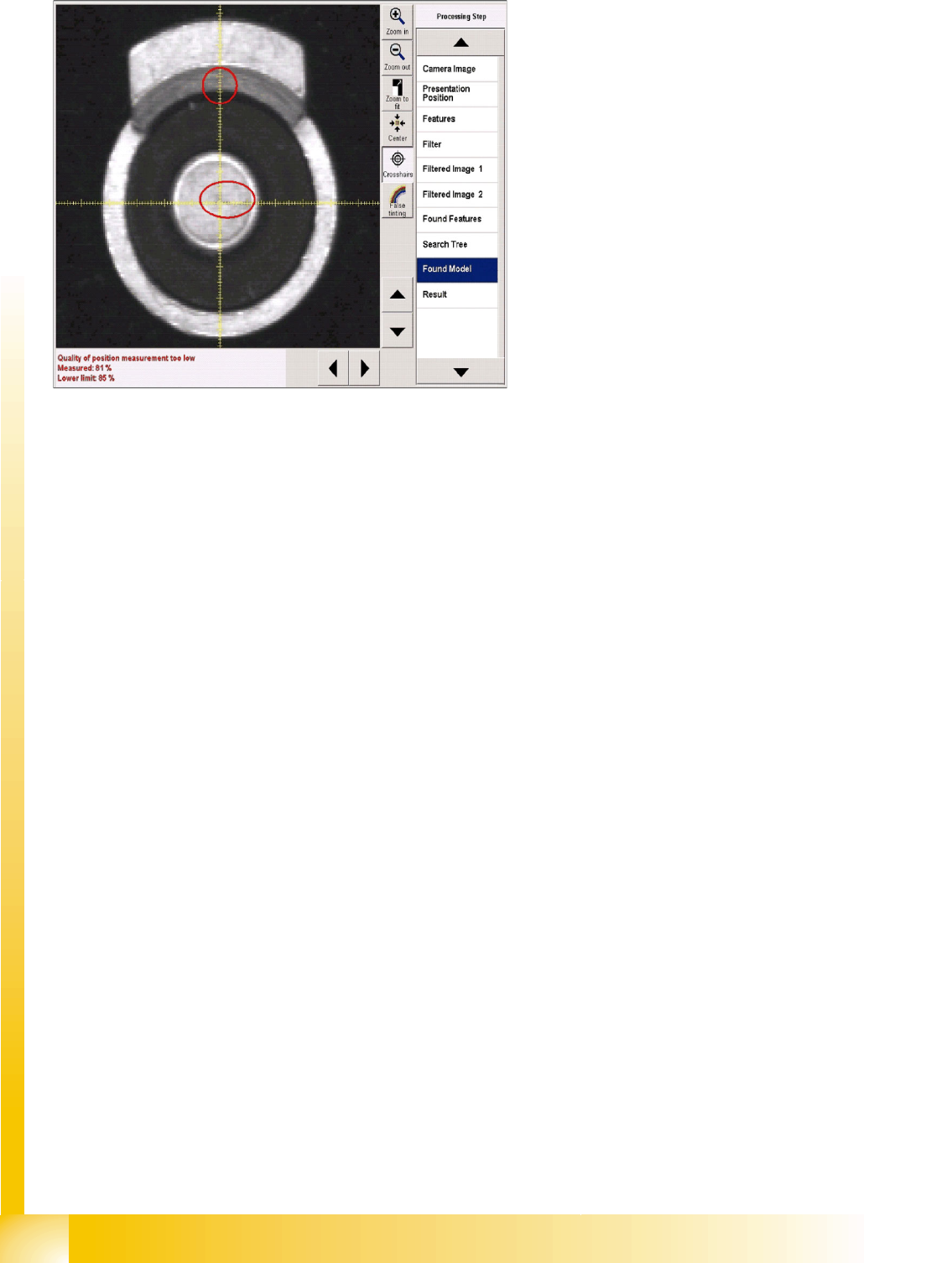
Error processing
If error messages are issued during the
recognition steps, the error reason will be
displayed in the results window, under the camera
image.
IN a corresponding recognition step, the
evaluation will be omitted (red rings) and the
steps for the subsequent component inspection
will not be available in the selection menu.
Component Shapes
SIPLACE Vision Image Export/Import New SIPLACE Vision Functions for 605 and 701 Station SW
Student Guide SIPLACE Vision (Customer)
Edition 12/2008 EN Component Shapes
101
5.4 New SIPLACE Vision Functions for 605 and 701 Station SW
Three new functions have been introduced for these 2 station software versions.
701/604.01: Export/import of the SIPLACE Vision images into a component shape description
including manipulation settings such as illumination and algorithms.
701: Robustness display for the teached component with the selected settings (also available in 605
SW at a later date)
605: Flux inspection of all component shape types for dipping before optical centering.
5.4.1 SIPLACE Vision Image Export/Import
In order to adopt modifications to the teached component shape, carried out in other systems, an import/
export function for SIPLACE Vision log files was implemented in SIPLACE Vision 701.
5.4.1.1 Export Function
The
Export Vision Data
option in the new SIPLACE
Vision
pull-down menu of the SIPLACE Vision
TeachStation creates an XML file including the data that were created by modifying the illumination or
the algorithms! This export function is not available at the placement station. Here, it is still sufficient to
save a SIPLACE Vision context file.
The SIPLACE Pro component shape export only exports the programmed standard data set without the
data that were created during teaching by means of modifying the illumination or the algorithms.
5.4.1.2 Import Function
This function is only available on the station with an active component camera.
Procedure:
X Provide the storage medium containing the XML file of the SIPLACE Vision TeachStation (result of
a SIPLACE Vision error analysis) in the station SW.
X In the component shape teach interface select the
Vision
und
Import Vision Data
pull-down menu
or the
Import Vision Data
menu button.
X Get the required component from the feeder in component shape teach mode.
X Select the
Import Vision Data
function and the required file on the storage medium.
X The programmer's sketch of the component shape will be displayed. Now it is necessary to test if the
selected settings really lead to a secure recognition of the components!
X If a secure component recognition is assured, quit the component shape teach menu and save the
data (including manipulated data such as illumination or algorithms if present) via
Save Data
to the
SIPLACE Pro computer.
NOTE: A "re-import" into SIPLACE Pro can only be carried out via the SIPLACE Vision
user interface of the station SW.
All SIPLACE Pro versions display an "incorrect XML format" if these files are directly re-imported
into SIPLACE Pro.
X For this reason it is helpful to use the same name for ...sensorXX.SVDMP and
...sensorxx.XML.
Component Shapes
New SIPLACE Vision Functions for 605 and 701 Station SW SIPLACE Vision Robustness Display
Student Guide SIPLACE Vision (Customer)
Component Shapes Edition 12/2008 EN
102
5.4.2 SIPLACE Vision Robustness Display
If a component shape is inspected or teached in the camera view, the given settings, the current
component characteristics or the position at the nozzle may lead to difficulties in recognition.
In order to recognize this and to take counter measures in advance the robustness display has been
introduced as another test and teach element within the SR/VR701.01 (station SW) in the SIPLACE
Vision area.
Of course, you have to begin with the original measurement of a correctly recognized component in order
to be able to carry out all measurements (up to 30) with modified parameters.
The robustness display also works for synthetic marks for PCB position recognition and for good / bad
recognition (ink spots). For "Pattern" fiducials however, modifying the feature size in the robustness test
is not possible for both PCB position and good / bad recognition.
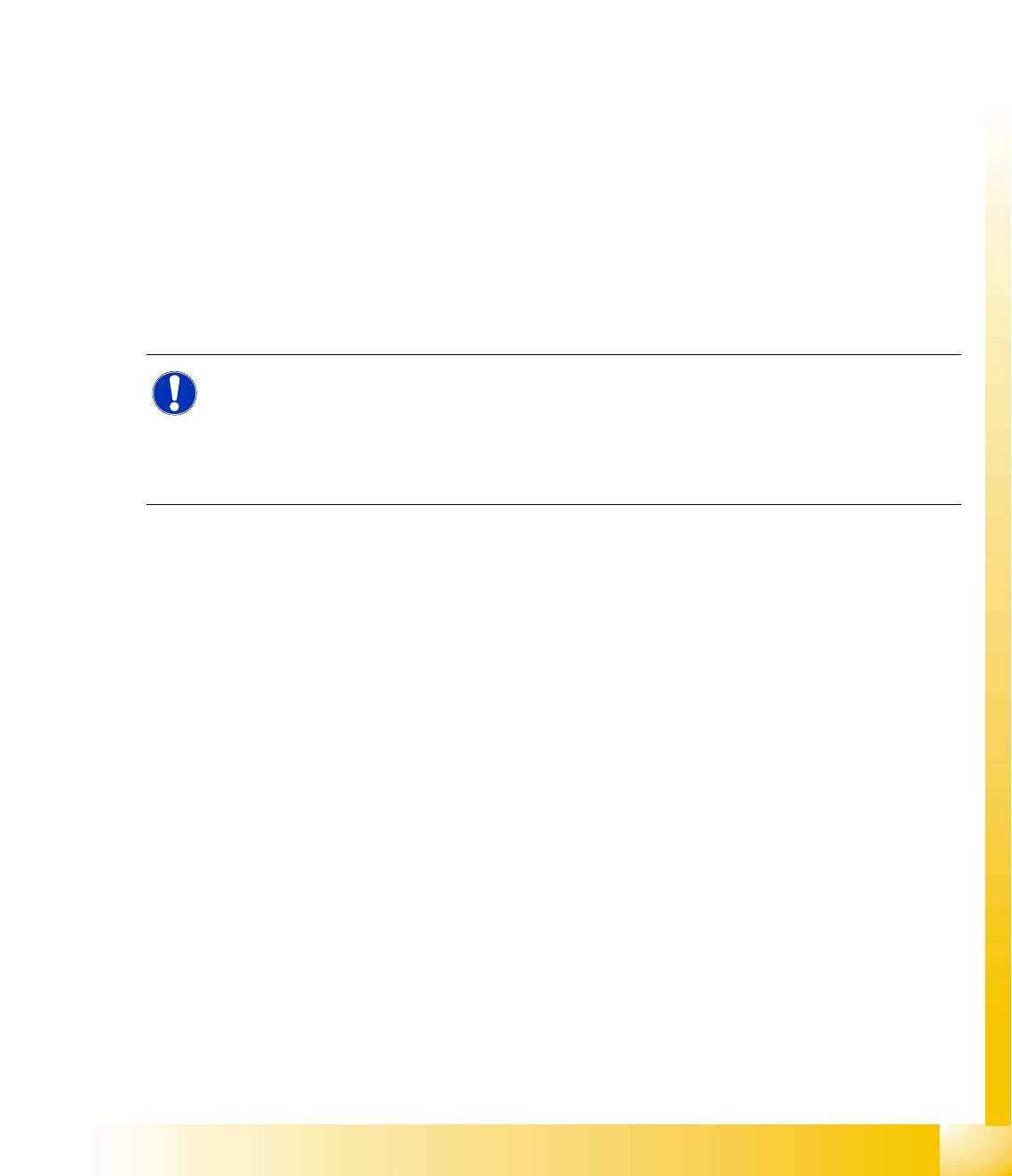
5.4.2.1 Interface for Robustness Display
5-2: User interface for SOT 23 robustness test
If the individual result fields of the robustness checks are selected, all measurement steps can be
provided and analyzed. The measurement result of this step is displayed as well.
Double-clicking on a measurement icon returns to the display of the original image.
A failure of the current measurement is shown by means of a red cross. The component will not be
placed. Measurement results that don't correspond to the real measurement values are shown by means
of an orange exclamation mark. Attention: the component will be placed in this CASE!
If a modification is carried out, a red field (measurement failed with an error) or a yellow field (inadequate
result or low tolerance) is placed next to the green tick of the current measurement in order to show that
a previous measurement step produced an error.