SIPLACE Vision Customer_en.pdf - 第103页
Component Shapes SIPLACE Vision Robu stness Display New SIPLACE Vision Functions for 605 and 701 Statio n SW S tudent Guide SIPLACE Vision (Customer) Edition 12/2008 EN Component Shapes 103 5-3: Robustness display after …
Component Shapes
New SIPLACE Vision Functions for 605 and 701 Station SW SIPLACE Vision Robustness Display
Student Guide SIPLACE Vision (Customer)
Component Shapes Edition 12/2008 EN
102
5.4.2 SIPLACE Vision Robustness Display
If a component shape is inspected or teached in the camera view, the given settings, the current
component characteristics or the position at the nozzle may lead to difficulties in recognition.
In order to recognize this and to take counter measures in advance the robustness display has been
introduced as another test and teach element within the SR/VR701.01 (station SW) in the SIPLACE
Vision area.
Of course, you have to begin with the original measurement of a correctly recognized component in order
to be able to carry out all measurements (up to 30) with modified parameters.
The robustness display also works for synthetic marks for PCB position recognition and for good / bad
recognition (ink spots). For "Pattern" fiducials however, modifying the feature size in the robustness test
is not possible for both PCB position and good / bad recognition.
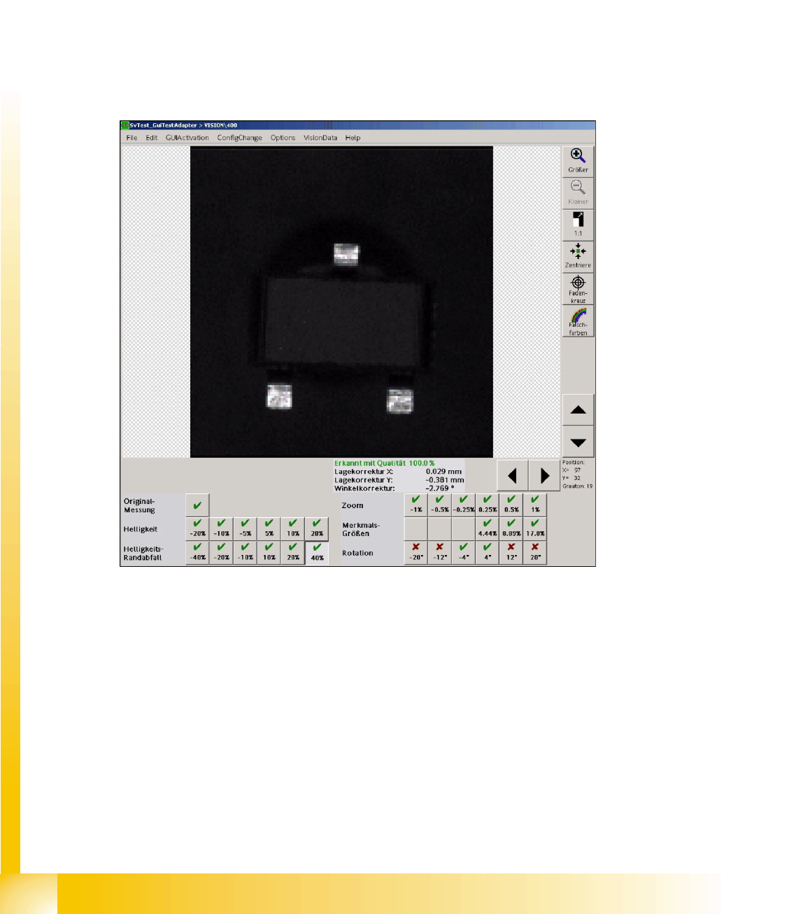
5.4.2.1 Interface for Robustness Display
5-2: User interface for SOT 23 robustness test
If the individual result fields of the robustness checks are selected, all measurement steps can be
provided and analyzed. The measurement result of this step is displayed as well.
Double-clicking on a measurement icon returns to the display of the original image.
A failure of the current measurement is shown by means of a red cross. The component will not be
placed. Measurement results that don't correspond to the real measurement values are shown by means
of an orange exclamation mark. Attention: the component will be placed in this CASE!
If a modification is carried out, a red field (measurement failed with an error) or a yellow field (inadequate
result or low tolerance) is placed next to the green tick of the current measurement in order to show that
a previous measurement step produced an error.
Component Shapes
SIPLACE Vision Robustness Display New SIPLACE Vision Functions for 605 and 701 Station SW
Student Guide SIPLACE Vision (Customer)
Edition 12/2008 EN Component Shapes
103
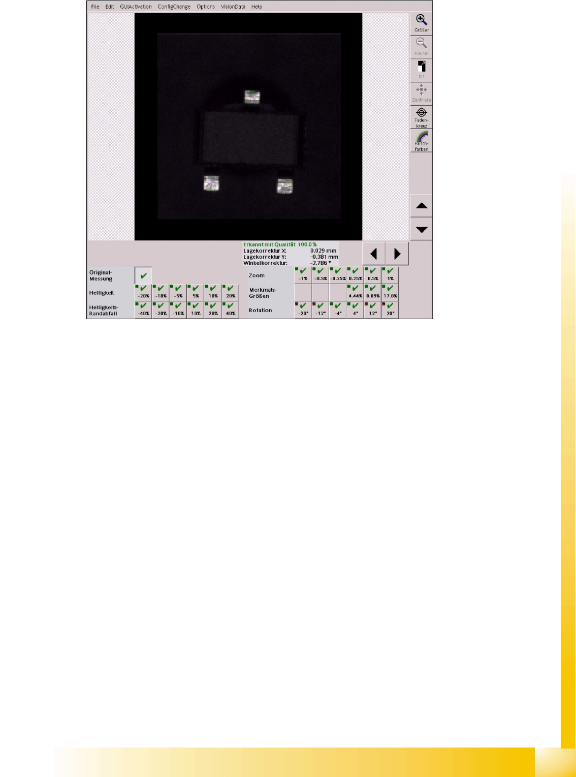
5-3: Robustness display after a "successful" modification
Here, the fields for
+/-20°-
und
+/-12°Rotation
show that this measurement is correct with respect to
the previous one.
5.4.2.2 Measurements in the Robustness Display
Based on the original measurement the following factors are modified:
Brightness is used to test deviations in brightness of individual components in another area.
Shading is used to test the uniformity of the image illumination for big components especially in
critical border areas of the camera field of view.
Scale is used to test deviations in size and the resulting measurement value.
FeatureSize is used to recognize increased or decreased features with the programmed
dimensions.
Rotation is used to recognize the filter positions for the features in different angle positions.
Component Shapes
New SIPLACE Vision Functions for 605 and 701 Station SW SIPLACE Vision Robustness Display
Student Guide SIPLACE Vision (Customer)
Component Shapes Edition 12/2008 EN
104
5.4.2.3 Brightness Modification
To allow a comparison between the original brightness and the maximum possible modification, at which
it is still possible to recognize the CHIP component example, the cursor is placed on the same shadow
point at the end of the left lead in the camera picture of the C&P20 camera (SST 23).
The most extreme illumination conditions are compared with the corresponding original image.
5-4: (1) Brightness value -20% at 178 – (2) Original illiumination at 230 – (3) Overexposed at +20% … at 255
The illumination values of the original image were set to default values in all 5 illumination levels (80/80/
80/120/180). If the illumination is too low, a brightness problem occurs in the robustness tests with
reduced illumination.
5-5: Brightness value reduced by 5%
At this brightness value, which is reduced by 5% with respect to the original picture, the leads can still
be found without rotation at the lead ends. All other measurement steps including the inspection succeed
despite the reduced brightness and the very matt lead surface.
Below, all measurement steps of the brightness values, for which the measurement fails, are shown: