SIPLACE Vision Customer_en.pdf - 第123页
Component Shapes Coplanarity Measurement for IVP 3D Coplan Coplanarity Measurement for Gullwing and Ball Leads S tudent Guide SIPLACE Vision (Customer) Edition 12/2008 EN Component Shapes 123 Station SW User Interface fo…
Component Shapes
Coplanarity Measurement for Gullwing and Ball Leads Coplanarity Measurement ILD2200
Student Guide SIPLACE Vision (Customer)
Component Shapes Edition 12/2008 EN
122
Measurement Basics
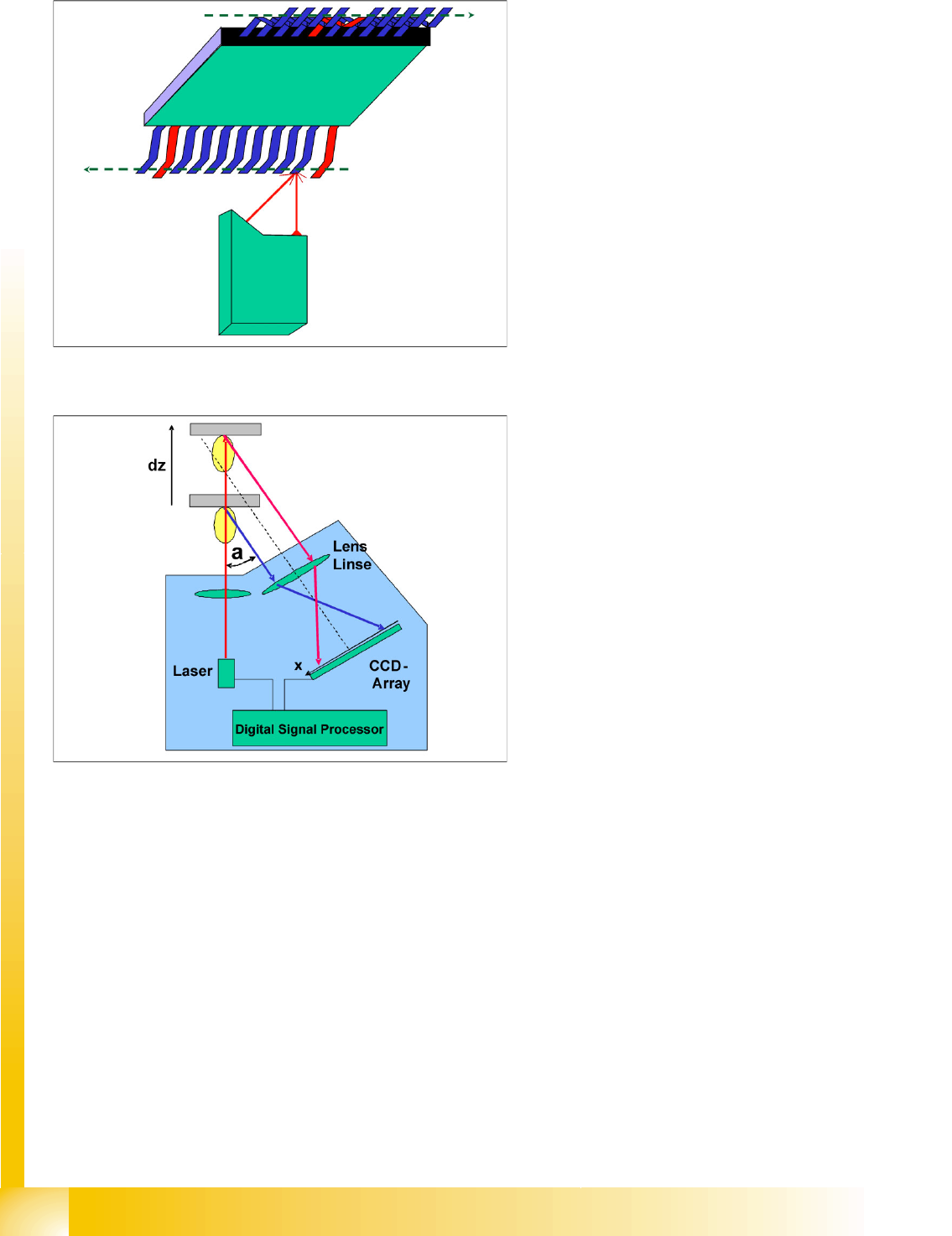
5-22: Measurement procedure for a SOxx component on the ILD2200
A spot laser beam is used to measure the contact
surfaces of the gullwing leads, with the
triangulation principle. The Z axis control function
for the TwinHead ensures stabile and precise
component height positioning during the
measurement process. The gantry axes move the
lead contact surfaces – in line with the preceding
optical centering by the stationary component
camera – exactly over the laser beam in the
direction of scanning and parallel to the
component edges.
5-23: Triangulation of the spot laser for determining the gullwing lead height
deviation
The lowest leads found during scanning determine
the contact level of the component. To ensure
reliable soldering of all leads, the highest lead may
not be higher than the solder paste height
specified in the PCB programming.
If the lead reflects the laser beam at a higher
position, the CCD sensor will recognize this
reflection below the center of the arrangement.
The signal processor and the evaluation system
for the station computer can then calculate the
lead height position.
Component Shapes
Coplanarity Measurement for IVP 3D Coplan Coplanarity Measurement for Gullwing and Ball Leads
Student Guide SIPLACE Vision (Customer)
Edition 12/2008 EN Component Shapes
123
Station SW User Interface for Coplanarity Measurement
5.6.2 Coplanarity Measurement for IVP 3D Coplan
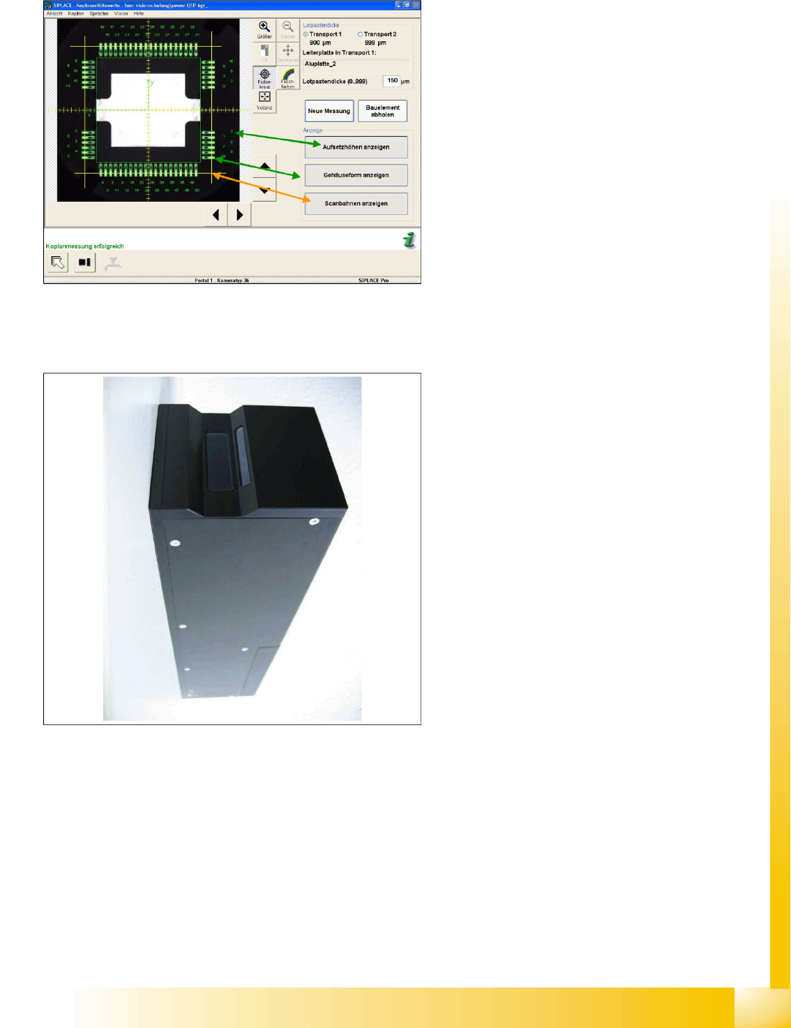
During CS testing, the component camera image
can display all relevant coplanarity measurement
data and the scanning paths used by the operator
during measurement.
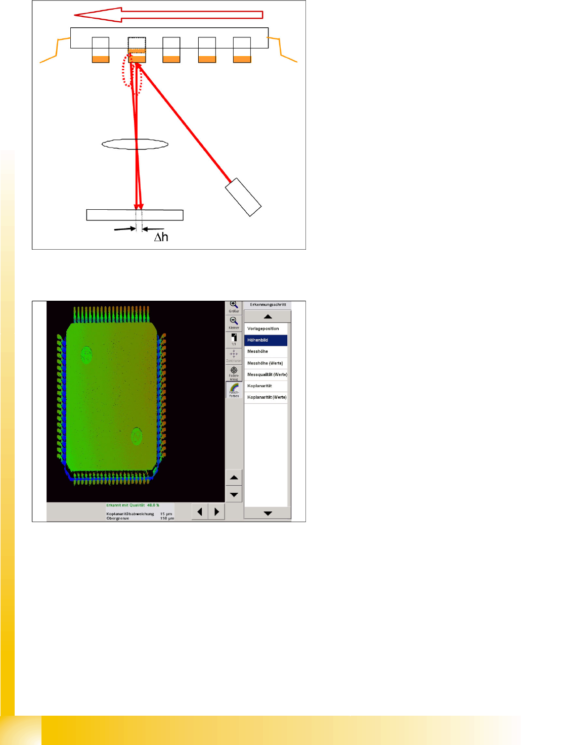
5-24: IVP 3D coplan sensor (laser class 2 in machine) for gullwings and ball
leads
In contrast to the coplanarity measurement with
ILD 2200, the measurement with the IVP 3-
D(imensional) coplan sensor uses a line laser. The
sensor needs its own computer. An X2 or X3
machine is therefore equipped with a TwinHead i
the second processing area and has a Vision
computer in addition to the station computer. This
sensor also supports coplanarity measurement on
BGA structures.
Component Shapes
Coplanarity Measurement for Gullwing and Ball Leads Coplanarity Measurement for IVP 3D Coplan
Student Guide SIPLACE Vision (Customer)
Component Shapes Edition 12/2008 EN
124
Measurement Basics for Gullwings
5-25: Triangulation of the line laser for determining the gullwing lead height
deviation
A line laser beam is used to measure the contact
surfaces of the gullwing leads, with the
triangulation principle. The Z axis control function
for the TwinHead ensures stabile and highly
precise component height positioning during Y
axis movement in the measurement process.
5-26: Measurement value for a QFP 80
The measured side deviation for diffuse reflections
on the leads is converted into the height deviation
of the lead.