SIPLACE Vision Customer_en.pdf - 第170页
SIPLACE Pro 3.0 Programming Interface for Componen t Shapes Handling Component Programming Reduced Acceleration Values S tudent Guide SIPLACE V ision (Customer) SIPLACE Pro 3.0 Programming Interface for Component Shapes …
SIPLACE Pro 3.0 Programming Interface for Component Shapes
Component Camera Selected Handling Component Programming
Student Guide SIPLACE Vision (Customer)
Edition 12/2008 EN SIPLACE Pro 3.0 Programming Interface for Component Shapes
169
7.4.1.2 Nozzle Assignment
Outer dimensions
The outer length or outer width shown in the diagram above can be used to determine possible
placement problems as these outer nozzle edges or the outer diameter could touch neighboring
components. In the case of extremely small nozzle tips, you can also determine whether these tips can
be inserted into the pickup pockets of the tape or whether they will be seated on the tape surface for
pickup.
Inner dimensions
7.4.2 Component Camera Selected
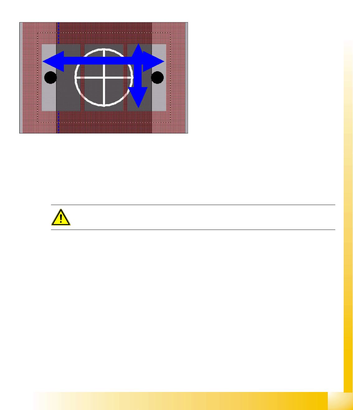
The camera field of vision shown can be used to determine whether a component with the specified
pickup tolerances can be optically centered. In the case of stationary cameras, you can see whether
multiple measurement is required. (precise Z positioning in the focal height is required for this) You will
not be able to see whether a camera has reached its specific limits.
This shows whether there is a risk that
components which are smaller than the nozzle
surface could be sucked in despite the nozzle
vertical separation which may be present. You can
also determine whether vacuum errors could
occur during component pickup, particularly when
the pickup tolerances are too great.
ATTENTION:
ONLY select
Deactivate Check for minimal Comp.shape structure
in rare exceptions!
SIPLACE Pro 3.0 Programming Interface for Component Shapes
Handling Component Programming Reduced Acceleration Values
Student Guide SIPLACE Vision (Customer)
SIPLACE Pro 3.0 Programming Interface for Component Shapes Edition 12/2008 EN
170
7.4.3 Reduced Acceleration Values
To avoid difficulties placing exotic components, you can reduce the acceleration values for all axes in
the placement machine.
To still keep the placement performance high, the programmed acceleration values are axis-specific and
nozzle-specific.
Because the machines have to perform many different conditions of acceleration please look into the list
of acceleration values in the SIPLACE Pro Online Help.
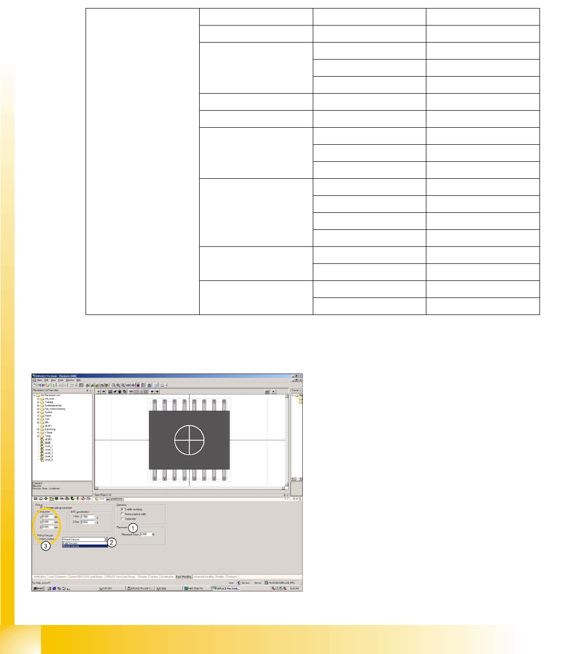
7.4.4 Basic Handling of Component Shapes
Z axis in g S-20 RV 12 5.30
S-23/CS RV 12 6.40
F4/F5/F5HM/CF RV 12 6.40
RV 6 5.30
P&P 1.30
HS50 RV 12 12.25
HS60 RV 12 15.29
D series RV 12 18.04
RV 6 9.41
P&P 4.90
X series
or
HF/HF3
RV 12 18.04
RV 6 9.41
P&P 4.90
C&P20 21.00
S25HM RV 12 12.25
RV 6 12.25
S27HM RV 12 12.25
RV 6 12.25
1. Enter the placement force. The placement
mode can be specified in the Advanced
Handling window and also enabled/disabled
there.
2. Early Vacuum is the only special mode which
can be enabled here.
3. A non-central pickup point for the component
shape can be programmed here. This does
not affect the component center, which is
referred to for component centering in the
Vision system. The pickup position correction
value for the feeder refers to this new
component pickup point and is added to it.
Please note that this function is only supported
in older machines with SC/MC 503.xx or
higher.
SIPLACE Pro 3.0 Programming Interface for Component Shapes
Advanced Handling of Component Shapes Handling Component Programming
Student Guide SIPLACE Vision (Customer)
Edition 12/2008 EN SIPLACE Pro 3.0 Programming Interface for Component Shapes
171
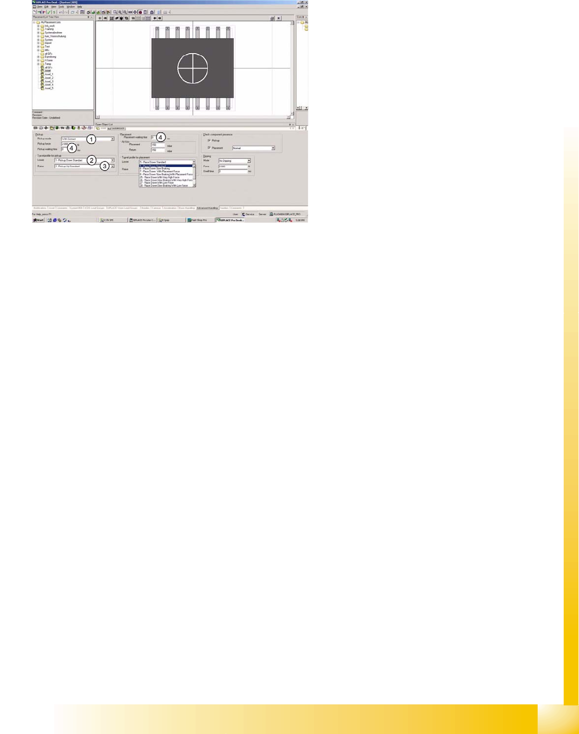
7.4.5 Advanced Handling of Component Shapes
The options listed below should be seen as
mutually exclusive alternatives for each point.
1. Pickup mode:
– With contact - nozzle makes contact with
component on pickup.
– Without contact - nozzle does not make
contact with component on pickup; nozzle
hovers several 1/100 mm above the
component surface.
2. Velocity profile :
– (1) Pickup, down, standard, with full speed
and relative position mode.
– (17) Pickup, down, without contact, with
full speed and absolute positioning mode.
– (21) Pickup, down, with low force - not
used.
– (22) Pickup, down, with very low force
(only with special nozzle) - not used.
3. Velocity profile :
– (2) Pickup, up, standard, with full speed
and no delay.
– (3) Pickup, up, with slow start to ensure
increased holding force at the nozzle.
– (4) Pickup, up, with creep start - not
recommended (waste of time).
4. Waiting times:
– During pickup, for specially constructed
customer feeders.
– During placement, for special component
handling at time of placement.