SIPLACE Vision Customer_en.pdf - 第15页
Introduction Individual Camera Types - Details Camera Overview S tudent Guide SIPLACE Vision (Customer) Edition 12/2008 EN Introduction 15 3.4.1.2 CO Camera C&P12 SST 28 3.4.1.3 CO Camera C&P6 (C&P12 'HR…
Introduction
Camera Overview Individual Camera Types - Details
Student Guide SIPLACE Vision (Customer)
Introduction Edition 12/2008 EN
14
Overview of stationary cameras and other sensors
3.4.1 Individual Camera Types - Details
3.4.1.1 CO Camera C&P20 SST 23
Parameters IC
camera
IC
camera
FC
camera
KOPLAN
ILD2200 (spot
laser)
3 D KOPLAN
IVP (line laser
ONLY X2/X3)
For placement head TWIN with IC
camera
D1 TWIN with
IC camera
TWIN with FC
camera
TWIN TWIN
SST 33 36 25 17 37
Resolution [µm] 41 80 16
Field of vision [mm²] 65 x 50 39 x 39 19 x 19
Min. CO size [mm²]
CHIP component with
designation
0.5 x 0.5
0402
0.8 x 0.8
0603
0.2 x 0.2
01005
Max. component size
[mm²] single measurement
55 x 45 32 x 32 16 x 16 50 x 50
Min. lead pitch [µm] 300 400 250 400 500
Min. lead width [µm] 150 240 100
Min. ball pitch [µm] 450 560 140 ---
Min. ball [µm] 250 320 80 --- 400
Illumination levels 6 6 6 --- ---
Teaching /centering the
component presentation
angle
90° steps /
placement
angle
90° steps /
placement
angle
90° steps /
placement
angle
Description
position
Description
position r. 90°
step
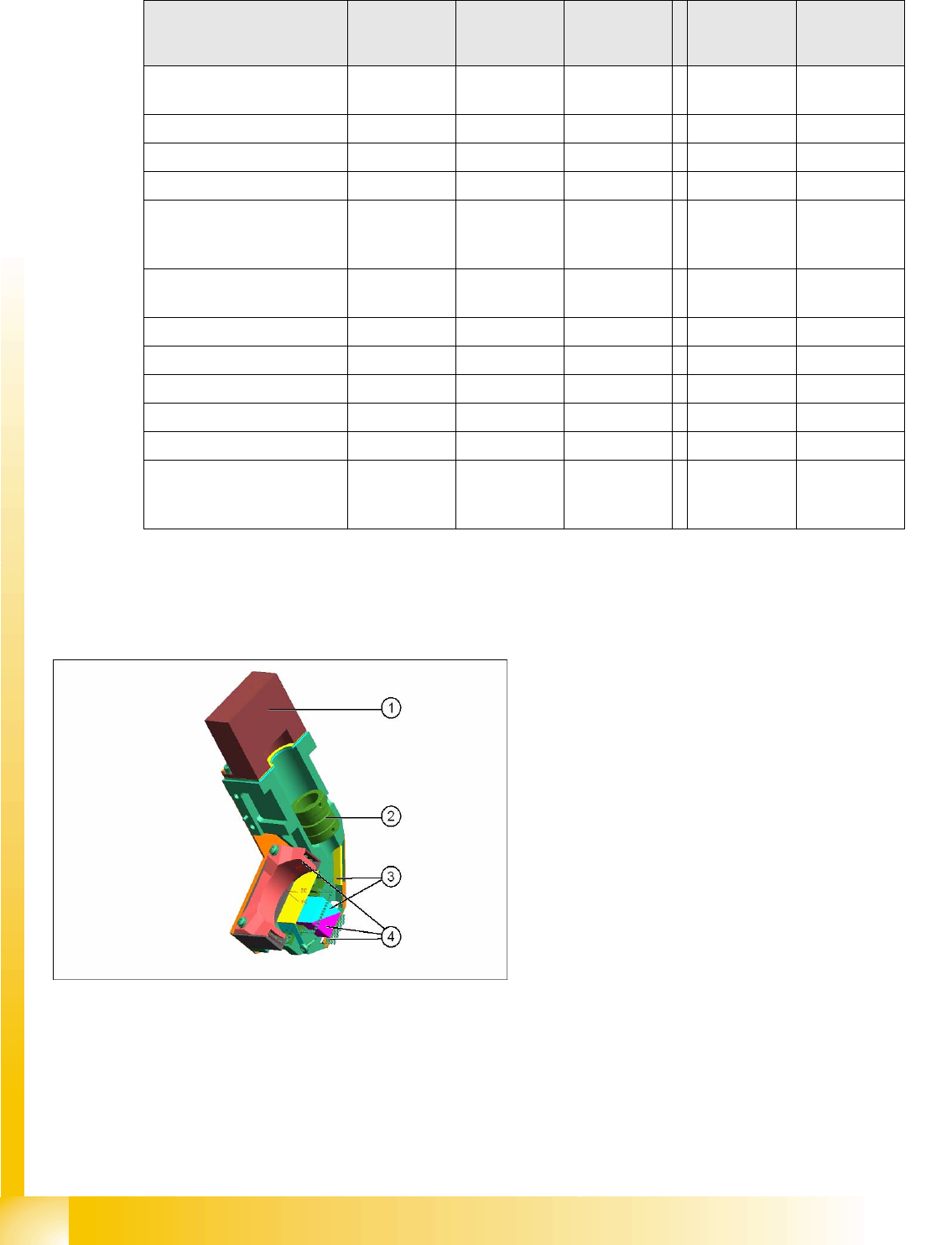
Legend
1. Camera sensor
2. Lens system
3. Mirror system
4. Five programmable illumination levels
Introduction
Individual Camera Types - Details Camera Overview
Student Guide SIPLACE Vision (Customer)
Edition 12/2008 EN Introduction
15
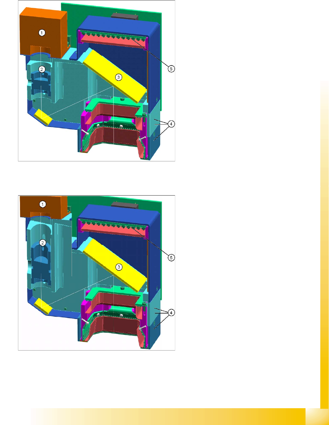
3.4.1.2 CO Camera C&P12 SST 28
3.4.1.3 CO Camera C&P6 (C&P12 'HR') SST 29
Legend
1. Camera sensor
2. Lens system
3. 45° mirror system
4. Three programmable illumination levels
5. 0° illumination level programmable
Legend
1. Camera sensor
2. Lens system
3. 45° mirror system
4. Three programmable illumination levels
5. 0° illumination level programmable
Introduction
Camera Overview Individual Camera Types - Details
Student Guide SIPLACE Vision (Customer)
Introduction Edition 12/2008 EN
16
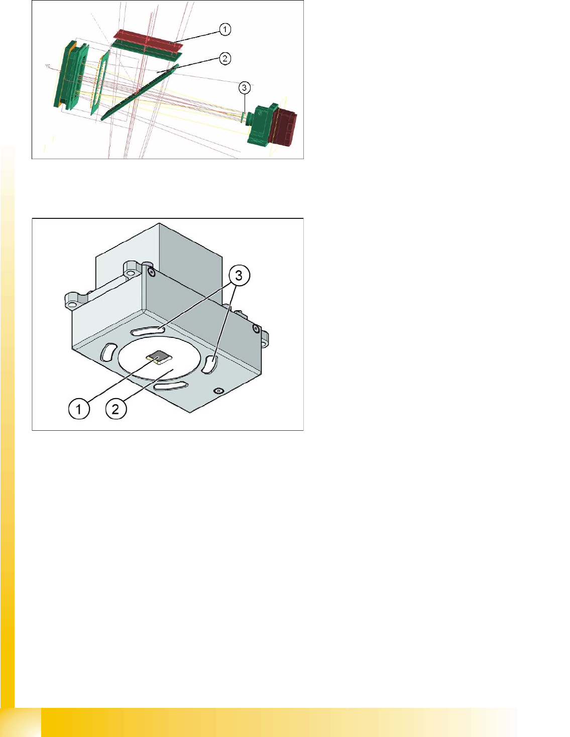
3.4.1.4 CO Camera TWIN 'IC' SST 33 ('FC' SST 25)
3.4.1.5 PCB Camera Standard SST34
Legend
1. 0° illumination
2. 45° mirror
3. Lens system with camera sensor;
further illumination levels near CO (left)
Legend
1. Direct red illumination
2. Diffuse red illumination
3. 4 openings for blue illumination at side