SIPLACE Vision Customer_en.pdf - 第151页
SIPLACE Vision - T eaching Fiducials Machine Functions Station SW Menu Functions Combined with 'Fiducials' S tudent Guide SIPLACE Vision (Customer) Edition 12/2008 EN SIPLACE Vision - T eaching Fiducials 151 6.…
SIPLACE Vision - Teaching Fiducials
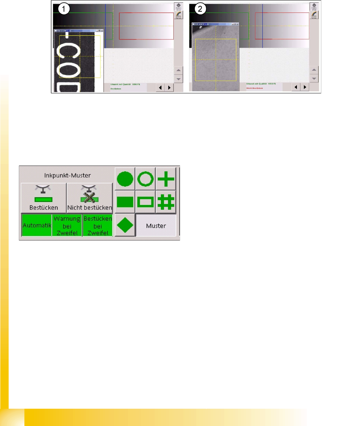
Fiducials for Good/Bad Recognition of panels Trained Inkspots
Student Guide SIPLACE Vision (Customer)
SIPLACE Vision - Teaching Fiducials Edition 12/2008 EN
150
6.3.3.4 Middle gray value
The evaluation diagram is similar to the template method, with a red marked bad case area and a green
marked good case area.
6-17: Dark fiducial for good case (1) and light label for bad case (2)
The light-colored label for the bad case state (2) causes the two classification areas to be "swapped"
with one another.
The threshold for the good area ranges up to gray values of 126 and the bad area begins in this example
at 140.
The bad state is on the right, on a bright background, and with a brightness of 155. The good state has
a medium gray value of 110.
Features
Fast procedure
The classification is based on the global features of the image. A defined shape is therefore not
required.
This procedure is sensitive to fluctuations in brightness, meaning that this method is not ideal when
used with lines which have different PCB camera brightnesses.
Once again, you need to perform a position recognition run before inkspot recognition.
In this example, if a fiducial is between 126 and
140, the following decisions can be made during
programming:
That components are to be placed
That components are not to be placed
That the operator is to be warned of this state
with a warning message
(to allow time for improvement e.g. through
crossing out the fiducial).
Switching on the "automatic function" terminates
the inkspot teaching procedure.
The function buttons
Placement
and
Do not
place
are only visible after the pattern button for
the inkspot has been selected.
SIPLACE Vision - Teaching Fiducials
Machine Functions Station SW Menu Functions Combined with 'Fiducials'
Student Guide SIPLACE Vision (Customer)
Edition 12/2008 EN SIPLACE Vision - Teaching Fiducials
151
6.4 Station SW Menu Functions Combined with 'Fiducials'
The station software offers a fiducial position correction function for incorrectly positioned PCBs. This
allows you to correct the position of the PCB position recognition fiducials and to then continue
placement.
6.4.1 Machine Functions
Gantries 2 and 4 or the left-hand gantry in the machine determine the PC position in the machine for the
placement process.
Error messages relating to the fiducial position are only issued for these gantries.
To rule out temperature influence for high-precision applications, gantries 1 and 3 or the right-hand
gantry in the machine measure the PCB position deviation, compared to the partner gantry for the 1st
PCB or the position fiducials for the next PCB, after a minimum of 300 seconds.
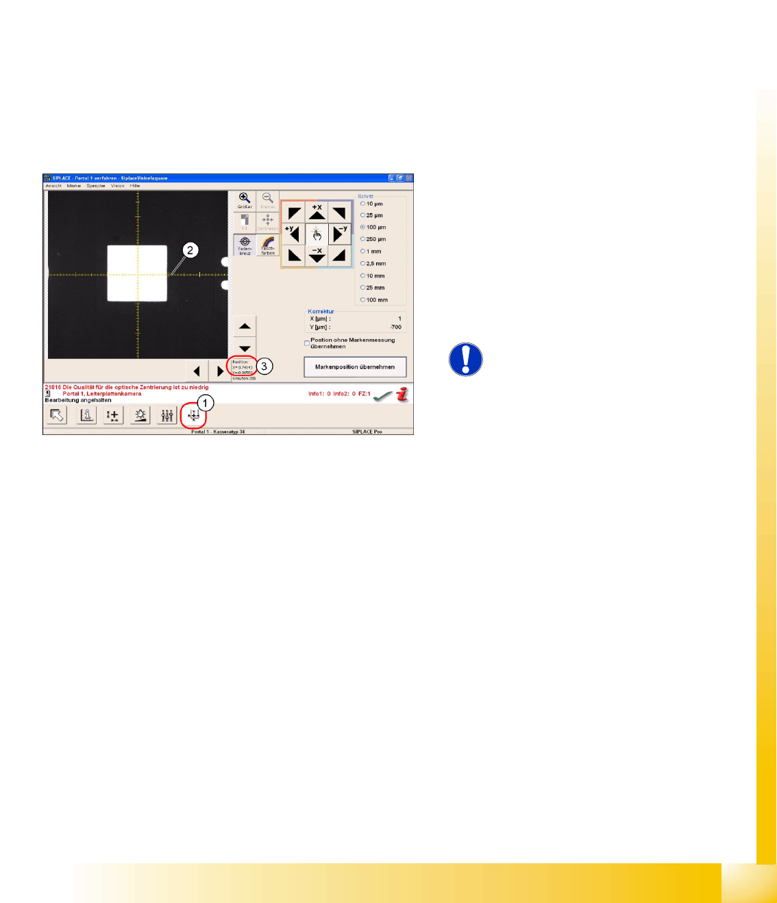
6.4.2 Fiducial Position Teaching
The position needs to be trained in 3 separate steps for each PCB position fiducial. After the error
message
Fiducial not found,
you can switch over to the fiducial teach menu for the teaching process.
The fiducial positions are only learnt for the placement process in the respective placement area of the
machine. When the PCB is transported out of the placement conveyor, the position offset of the fiducial
is set back to 0.
If this position offset was caused by a programming error, you will need to perform correction in SIPLACE
Pro.
In this menu you can also open other SIPLACE Vision fiducial teaching functions and then save their
respective results after editing.
6-18: Teaching the fiducial position
The PCB fiducial position is shown in the
SIPLACE Vision fiducial teach menu as a position
teach menu (1).
The X axis (2) of the camera position shows
0.7 mm (3), this being the original gantry position
before correction (7 marker lines on the coordinate
cross) and therefore points to the fiducial center
through movement of the gantry.
NOTE:
Due to the camera installation, X
cam1
-
corresponds to the - Y
P1
coordinate.
SIPLACE Vision - Teaching Fiducials
Feeder Position Recognition Fiducials Component Pocket Fiducials
Student Guide SIPLACE Vision (Customer)
SIPLACE Vision - Teaching Fiducials Edition 12/2008 EN
152
6.5 Feeder Position Recognition Fiducials
There is a special type of fiducial available for feeder position recognition.
In this section we will not cover the feeder position recognition function in the machine but merely touch
on the basic functions which SIPLACE Vision makes available for this.
The optical recognition is performed by enabling the Vision interface in the "setup staff" operator level,
during the startup sequence.
This fiducial, specified as a component pocket in SIPLACE Pro, can be programmed to a maximum size
of 2x2 mm.
6.5.1 Component Pocket Fiducials
X feeders
S feeders
Only those fiducials which support the pickup
position with component in the 8 mm tape pocket
are made available for X feeders. The fiducial is
automatically generated from the CS body data, if
the component length is 1.0 mm (0402) or less. If
the component is larger, feeder position
recognition can not be forced even by teaching a
pickup position fiducial.
There are 2 methods of feeder position recognition
for S feeders (for 8 mm feeders only):
Pickup position fiducials (tape pockets)
When components with a length of 0.6 mm or
shorter are in the 0201(01005) 3x8 mm S
feeder.