SIPLACE Vision Customer_en.pdf - 第43页
Component Shapes Overview of Component Shapes Which Require Separate Grou p Descriptions Component Shape Description Rules S tudent Guide SIPLACE Vision (Customer) Edition 12/2008 EN Component Shapes 43 5.2 Component Sha…
Component Shapes
Structure of Component Shape Data Overview of Component Shapes Which Require Separate Group Descriptions
Student Guide SIPLACE Vision (Customer)
Component Shapes Edition 12/2008 EN
42
5.1.2 Overview of Component Shapes Which Require Separate Group Descriptions
CS type name Lead groups- separation
required?
Reason
Shield Required without exception,
due to new algorithms
SIPLACE Vision uses corner recognition or polygon circle
recognition. ICOS uses virtual leads or ball descriptions.
CCGA Not important SIPLACE Vision recognizes column leads. ICOS processes
these components as BGAs.
BGA and
CCGA
Possibly required If (to save time) not all leads have been activated or programmed
for the inspection mode (for ICOS).
Plug Possibly required SIPLACE Vision permits all types of leads. ICOS does not allow
any combination of leads.
Nonstandard Possibly required SIPLACE Vision can center lead types which would need to be
omitted for ICOS e.g. lead-ball combinations etc.; BLOP leads;
leads with notches or rounded corners.
BareDie Possibly required if the PDC
description for ICOS needs to
be used.
Chip COs were described without leads (PDC).
Where possible, replace all lead-less descriptions!
(Use as regular FDC in LC for ICOS.)
Components
with special
descriptions for
ICOS
Important e.g. 2 pin diodes (SOD 323) need to be processed with a chip or
BGA description in ICOS, so that COs which are picked up from
the side can be sorted out.
For component shapes with lead feature combinations for
SIPLACE Vision.
All COs with
white bodies
and metallic
leads on them
Important, if SIPLACE Vision
is to recognize these features.
White CO bodies must be programmed as white bodies (often as
CHIP with virtual leads on the narrow sides) in ICOS. Due to
improved camera illumination technology, SIPLACE Vision now
supports the recognition of metal surfaces on a white
background.
Component Shapes
Overview of Component Shapes Which Require Separate Group Descriptions Component Shape Description Rules
Student Guide SIPLACE Vision (Customer)
Edition 12/2008 EN Component Shapes
43
5.2 Component Shape Description Rules
For process reliability reasons, SIPLACE Vision checks the CO geometry more exactly than SIPLACE
ICOS. Dimension tolerances up to approx. 30% are considered acceptable; tolerances between 30-40%
could influence the measurement procedure; values above 50% will not be accepted.
General component shape description rules
In most cases, the component shapes are not symmetrical to a particular point. To guarantee uniform
programming, please observe the following rules:
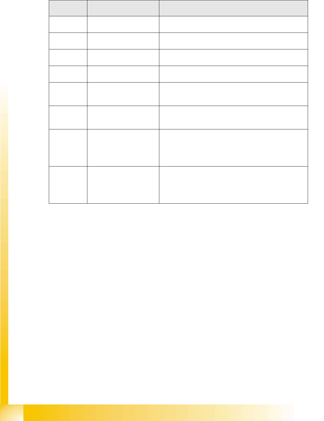
We recommend that you describe components in a horizontal position in SIPLACE Pro, not in a
vertical position:
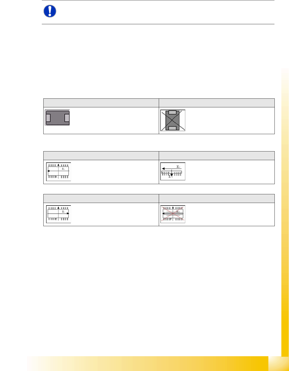
The coordinate system for CS descriptions in SIPLACE Vision is defined as follows:
NOTE: Observe the tolerances!
The tolerance values for lead dimensions must NOT exceed 50%, otherwise error messages
will be issued!
Horizontal: Not vertical:
View from above in SIPLACE Vision: View from side in SIPLACE Vision:
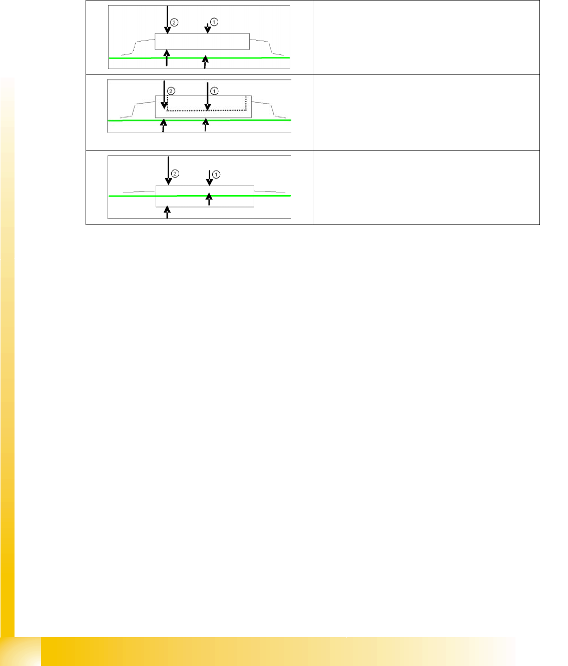
View from above in SIPLACE Pro: Do not use the view from below:
Component Shapes
Component Shape Description Rules Overview of Component Shapes Which Require Separate Group Descriptions
Student Guide SIPLACE Vision (Customer)
Component Shapes Edition 12/2008 EN
44
CO Height
The overall height Z (with lead 1) is used to calculate the Z-axis speed profile during (pickup and)
placement; to calculate the camera focal levels; the focus height position for the Coplanarity option and
the Z-position for the gantry positioning during placement with the TWIN head.
To define the heights of through-hole contacts, centering and locking pins, each case must be
considered individually and requires exact knowledge of the dimensions!
CO thickness
The Z body size (CO thickness 2) must be correctly programmed for the CO sensor installed in the C&P
20 head or for the CO sensor option on the DLM 1/2 C&P 12 head. In addition, take care that the height
is described correctly, so that the combination of CO and nozzles can be brought into the correct focal
range of the CO camera. The ICOS descriptions could include body dimensions with intermediate
values, by which the tolerance levels were set relatively high (common CS for R and C). In reality, these
values are the same as the overall Z value, since the additional lead heights are within the set height
tolerance.
Z body dimensions (component center height )
The Z body dimension (component center height ) must be described correctly, to guarantee various
functions, particularly the following:
Height measurement:
By the CO sensor on the C&P20 head or for the CO sensor option on the C&P12 head (DLM1 & 2).
Component measurement:
So that a combination of components and nozzles can be brought into the correct focal range of the
component camera.
Reliable pickup and optimum placement speed:
Overall height (with leads) is needed for calculating the Z-axis speed profile.
NOTE: In ICOS descriptions, the Z dimensions are not specified correctly. The tolerances were then set
appropriately larger.
Standard SMD CO
1. CO Height
2. CO thickness (for CO sensors)
Socket SMD CO
1. CO height (if the component height is programmed as
high as the socket edge, this is to be programmed as
a positive (!) Z pickup position correction (inner depth
of socket). (This may be necessary for the
precedence finder from SIPLACE PRO 6.0)
2. (2) CO thickness (for CO sensors)
Special CO in PCB cuts-outs
1. CO Height
2. CO thickness (for CO sensors)