SIPLACE Vision Customer_en.pdf - 第124页
Component Shapes Coplanarity Measurement for Gullwing and Ball Leads Coplan arity Measurement for IVP 3D Coplan S tudent Guide SIPLACE V ision (Customer) Component Shapes Edition 12/2008 EN 124 Measurement Basics for Gul…
Component Shapes
Coplanarity Measurement for IVP 3D Coplan Coplanarity Measurement for Gullwing and Ball Leads
Student Guide SIPLACE Vision (Customer)
Edition 12/2008 EN Component Shapes
123
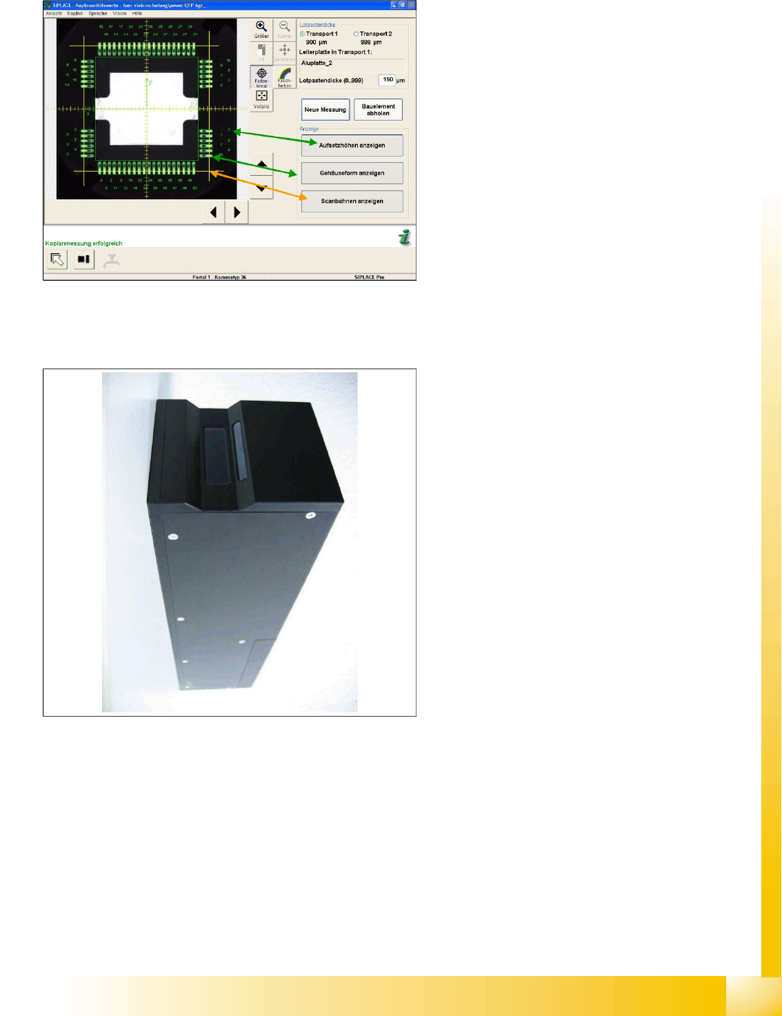
Station SW User Interface for Coplanarity Measurement
5.6.2 Coplanarity Measurement for IVP 3D Coplan
During CS testing, the component camera image
can display all relevant coplanarity measurement
data and the scanning paths used by the operator
during measurement.
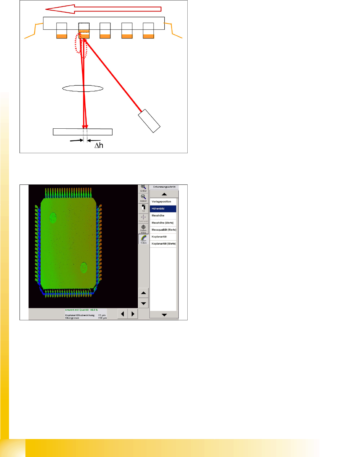
5-24: IVP 3D coplan sensor (laser class 2 in machine) for gullwings and ball
leads
In contrast to the coplanarity measurement with
ILD 2200, the measurement with the IVP 3-
D(imensional) coplan sensor uses a line laser. The
sensor needs its own computer. An X2 or X3
machine is therefore equipped with a TwinHead i
the second processing area and has a Vision
computer in addition to the station computer. This
sensor also supports coplanarity measurement on
BGA structures.
Component Shapes
Coplanarity Measurement for Gullwing and Ball Leads Coplanarity Measurement for IVP 3D Coplan
Student Guide SIPLACE Vision (Customer)
Component Shapes Edition 12/2008 EN
124
Measurement Basics for Gullwings
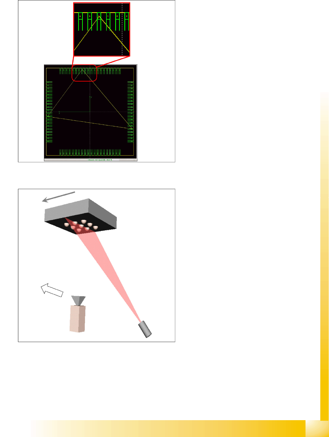
5-25: Triangulation of the line laser for determining the gullwing lead height
deviation
A line laser beam is used to measure the contact
surfaces of the gullwing leads, with the
triangulation principle. The Z axis control function
for the TwinHead ensures stabile and highly
precise component height positioning during Y
axis movement in the measurement process.
5-26: Measurement value for a QFP 80
The measured side deviation for diffuse reflections
on the leads is converted into the height deviation
of the lead.
Component Shapes
Coplanarity Measurement for IVP 3D Coplan Coplanarity Measurement for Gullwing and Ball Leads
Student Guide SIPLACE Vision (Customer)
Edition 12/2008 EN Component Shapes
125
Measurement Basics for BGA Leads
The lowest leads determined during scanning
(height 0) are set as the coplanarity level. The
component center must be inside this area (as
also for ILD2200). The deviation of other leads to
this is shown as a figure on the contact level of
each lead.
A line laser beam is used to measure the
hemispherical surfaces of the BGA leads, with the
triangulation principle (light breaking method).
This measures the ball arrangement as if in a
cross section diagram.