SIPLACE Vision Customer_en.pdf - 第125页
Component Shapes Coplanarity Measurement for IVP 3D Coplan Coplanarity Measurement for Gullwing and Ball Leads S tudent Guide SIPLACE Vision (Customer) Edition 12/2008 EN Component Shapes 125 Measurement Basics for BGA L…
Component Shapes
Coplanarity Measurement for Gullwing and Ball Leads Coplanarity Measurement for IVP 3D Coplan
Student Guide SIPLACE Vision (Customer)
Component Shapes Edition 12/2008 EN
124
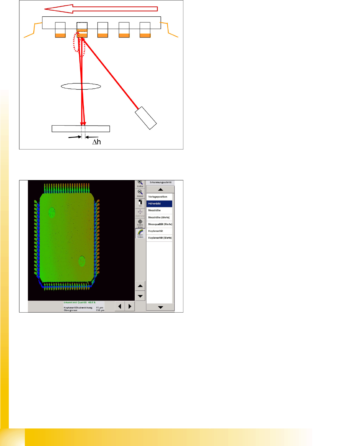
Measurement Basics for Gullwings
5-25: Triangulation of the line laser for determining the gullwing lead height
deviation
A line laser beam is used to measure the contact
surfaces of the gullwing leads, with the
triangulation principle. The Z axis control function
for the TwinHead ensures stabile and highly
precise component height positioning during Y
axis movement in the measurement process.
5-26: Measurement value for a QFP 80
The measured side deviation for diffuse reflections
on the leads is converted into the height deviation
of the lead.
Component Shapes
Coplanarity Measurement for IVP 3D Coplan Coplanarity Measurement for Gullwing and Ball Leads
Student Guide SIPLACE Vision (Customer)
Edition 12/2008 EN Component Shapes
125
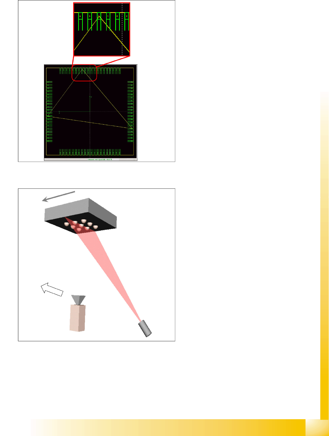
Measurement Basics for BGA Leads
The lowest leads determined during scanning
(height 0) are set as the coplanarity level. The
component center must be inside this area (as
also for ILD2200). The deviation of other leads to
this is shown as a figure on the contact level of
each lead.
A line laser beam is used to measure the
hemispherical surfaces of the BGA leads, with the
triangulation principle (light breaking method).
This measures the ball arrangement as if in a
cross section diagram.
Component Shapes
Coplanarity Measurement for Gullwing and Ball Leads Coplanarity Measurement for IVP 3D Coplan
Student Guide SIPLACE Vision (Customer)
Component Shapes Edition 12/2008 EN
126
Differences to Lead Coplanarity
For this purpose, the CS Editor provides a 3D coplanarity tolerance value for editing (0.3 mm for 0.1 mm
solder paste thickness or similar) in the
Basic Handling
menu - when coplanarity measurement is active.
you can choose whether the measurement is to be repeated (
Do not reject if measurement fails
) if
incorrect measurement occurs (highly sensitive to focus height).
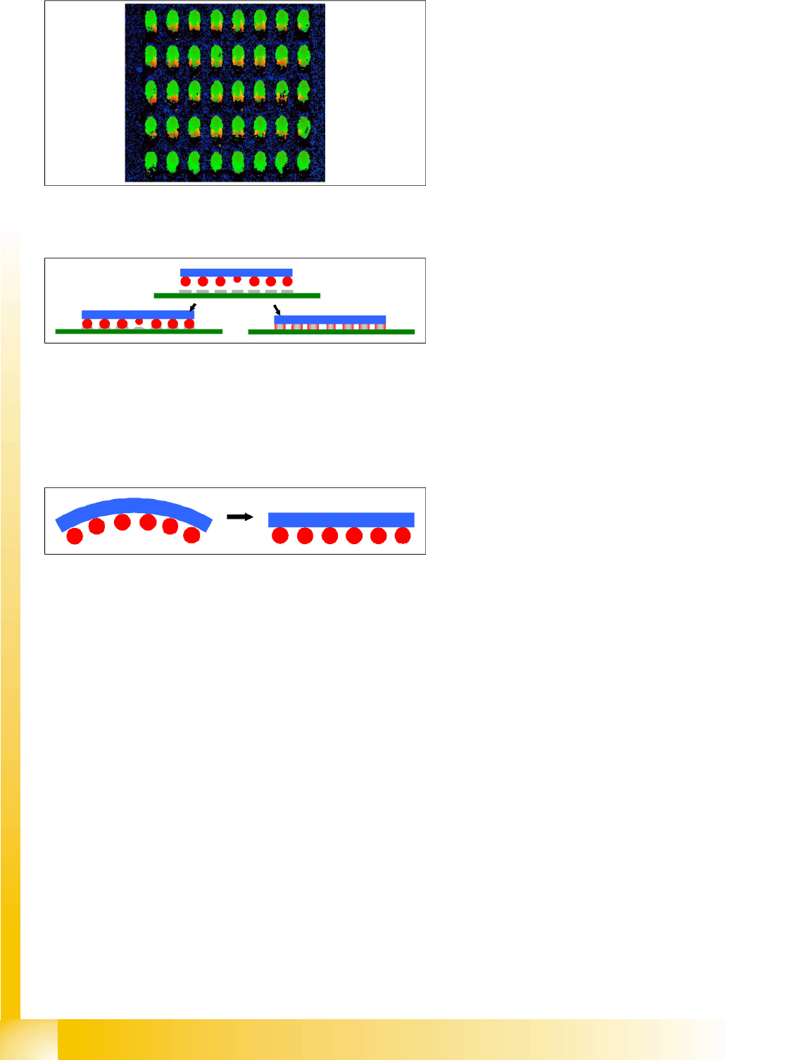
The ball height image shows areas without
measurement results (black) in the shadow of the
balls.
However, there are also reflections from
neighboring balls, which are shown as so-called
secondary reflections (red/yellow) or bright areas.
Direct reflections on the ball domes are a problem
for this sensor. If this problem occurs, you may
need to perform coplanarity measurement at a
different angle.
When soldering the balls of BGA components, an
additional "collapsing" of the hemispherical solder
balls can occur. This means that a ball might still
be soldered well even if it is outside the solder
paste height tolerance. The diagram on the right
shows this situation in which the component balls
collapse during soldering. The partial diagram on
the left shows the soldering state if the balls
remain stabile during a measured coplanarity
deviation.
The body of the BGA components could also
relax, meaning that the balls which are outside the
coplanarity tolerance would contact correctly
during reflow soldering.