SIPLACE Vision Customer_en.pdf - 第128页
SIPLACE Vision - Teaching Fiducials What are Fiducials? S tudent Guide SIPLACE V ision (Customer) SIPLACE Vision - T eaching Fiducials Edition 12/2008 EN 128 The fiducia l can only be trained, teste d or used f or placem…
SIPLACE Vision - Teaching Fiducials
What are Fiducials?
Student Guide SIPLACE Vision (Customer)
Edition 12/2008 EN SIPLACE Vision - Teaching Fiducials
127
6 SIPLACE Vision - Teaching Fiducials
6.1 What are Fiducials?
Fiducials consist of the following parts:
The optically recognizable structures which are used in the SIPLACE Vision system, for defining the
geometry, illumination and other programmable parameters and
The coordinate data.
These are made known to the SIPLACE Pro system, through the PCB programming.
Fiducials are optically recognizable geometric
structures which, as a rule, are not integrated into
the placement and/or electrical function of the
PCB. If no own fiducial structures are available,
contacts or other measuring points which remain
free of soldering paste can be used as fiducials.
Fiducials on a board (PCB) are used for the
following purposes:
PCB position recognition (for definition of the
placement position),
Good/bad board recognition (so-called inkspot
recognition) and
For accurate determination of the component
placement position.
SIPLACE Vision - Teaching Fiducials
What are Fiducials?
Student Guide SIPLACE Vision (Customer)
SIPLACE Vision - Teaching Fiducials Edition 12/2008 EN
128
The fiducial can only be trained, tested or used for placement, if the fiducial coordinates for the PCB are
known and have been sent to the machine.
Fiducials are approached in the following order during testing or placement:
PCB position recognition fiducials
Inkspot fiducials (global inkspot first; - also in bad case – and then the local inkspot fiducials of the
panels).
Component placement position fiducials.
If fiducials are trained, the operator determines the order of these fiducials through his selection. If the
position tolerance values are not set to maximum tolerance for all fiducials, the size of the tolerance field
will determine the order of PCB recognition fiducials. The fiducial with the greatest tolerance will be
approached first and that with the smallest tolerance will be approached last.
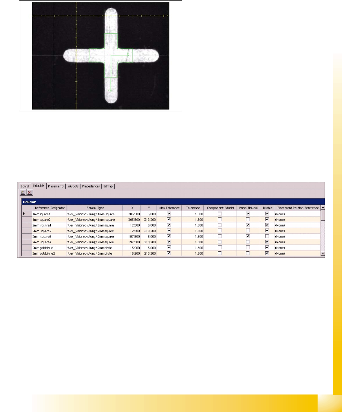
The SIPLACE Pro coordinate data includes:
The PCB/panel assignment
The fiducial position coordinates (X, Y)
The position tolerance data and
Use on the respective PCB (position
recognition fiducial; inkspot fiducial; placement
position fiducial).
It may also make sense to program more
fiducial coordinates and numbers and to
temporarily omit them when not needed.
SIPLACE Vision - Teaching Fiducials
PCB Position Recognition Fiducials in the PCB Layout What are Fiducials?
Student Guide SIPLACE Vision (Customer)
Edition 12/2008 EN SIPLACE Vision - Teaching Fiducials
129
6.1.1 PCB Position Recognition Fiducials in the PCB Layout
The number of fiducials in the PCB layout results in the following options for placement quality
optimization:
1 fiducial The X/Y position of the PCB can be measured in the conveyor - placement area of the
machine. ATTENTION: Is not sufficient for SIPLACE machines and is blocked by the SW.
2 fiducials The X/Y position of the PCB and the PCB angular position can be determined in the
conveyor - placement area of the machine. This is the minimum required for SIPLACE machines!
3 fiducials If the fiducials are arranged appropriately on the PCB layout (L shaped), a PCB offset can
be recognized and corrected.
More than 3 fiducials can be programmed, although only the first 3 will be used. When using the
long board option, up to 6 programmed fiducials are used, depending on the relevant placement
stop. There is also a possibility that coordinates are programmed for multiple coordinates but are
then intentionally deactivated.
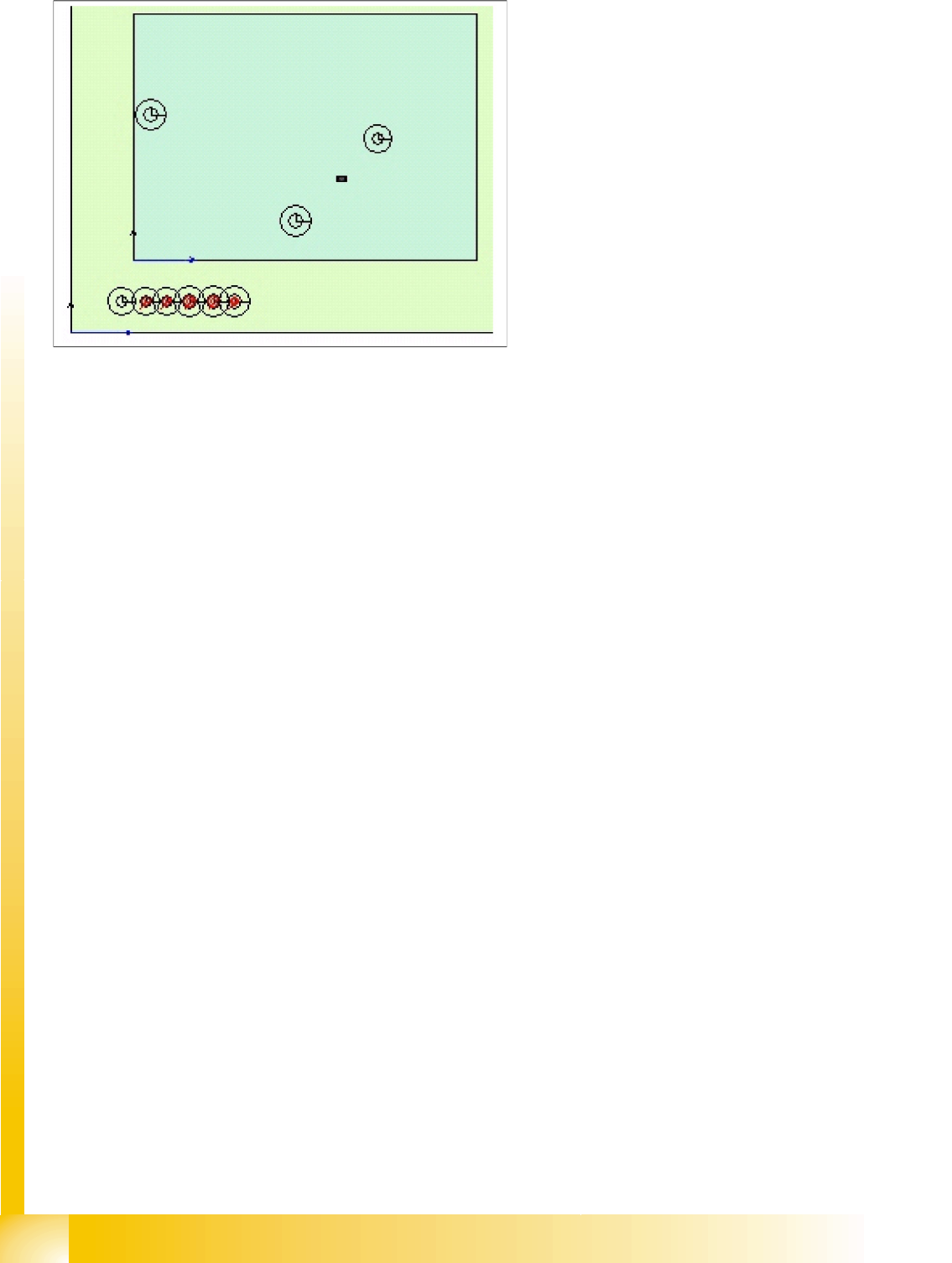
The arrangement of fiducials can be more or less favorable for the placement process.
6-1: Favorable arrangement of PCB position recognition fiducials
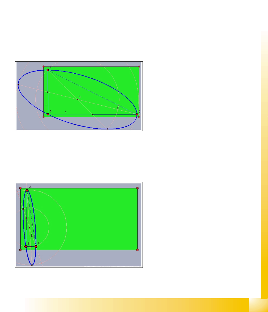
The following accuracy parameters apply for
extreme accuracy requirements:
If a position error occurs during fiducial
recognition, a placement error in the vicinity of the
central position (the intersection of the medians) of
the triangles would be approx. 0.6 x fiducial
measurement error.
In the area of the ellipse, the error would be as
large as the measurement error during position
recognition.
In the area of the double ellipse, the placement
error would also be doubled.These geometric
relations are independent of the Vision system and
should encourage you when selecting the fiducials
to take at least half the PCB dimensions as the
distance between fiducials.
6-2: Non-recommendable arrangement of PCB position recognition fiducials
If the distance of the fiducials programmed for
PCB position recognition was as near as in items
B and C, the right PCB edge would show a PCB
position recognition measurement error as a
multiplied (in this case about 20 fold) placement
position error.
A PCB production offset along the length would
not be recognized here.
This discussion about the two fiducial position
layouts should encourage you to select the
fiducials wisely.
If the programmed distances for the position
recognition fiducials on the whole PCB are not
observed, some SW versions will issue a
plausibility error.