SIPLACE Vision Customer_en.pdf - 第172页
SIPLACE Pro 3.0 Programming Interface for Componen t Shapes Handling Component Programming Advanced Handling of Component Shapes S tudent Guide SIPLACE V ision (Customer) SIPLACE Pro 3.0 Programming Interface for Compone…
SIPLACE Pro 3.0 Programming Interface for Component Shapes
Advanced Handling of Component Shapes Handling Component Programming
Student Guide SIPLACE Vision (Customer)
Edition 12/2008 EN SIPLACE Pro 3.0 Programming Interface for Component Shapes
171
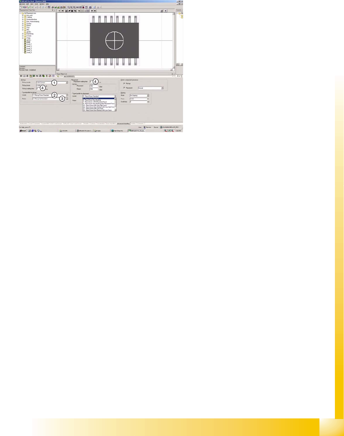
7.4.5 Advanced Handling of Component Shapes
The options listed below should be seen as
mutually exclusive alternatives for each point.
1. Pickup mode:
– With contact - nozzle makes contact with
component on pickup.
– Without contact - nozzle does not make
contact with component on pickup; nozzle
hovers several 1/100 mm above the
component surface.
2. Velocity profile :
– (1) Pickup, down, standard, with full speed
and relative position mode.
– (17) Pickup, down, without contact, with
full speed and absolute positioning mode.
– (21) Pickup, down, with low force - not
used.
– (22) Pickup, down, with very low force
(only with special nozzle) - not used.
3. Velocity profile :
– (2) Pickup, up, standard, with full speed
and no delay.
– (3) Pickup, up, with slow start to ensure
increased holding force at the nozzle.
– (4) Pickup, up, with creep start - not
recommended (waste of time).
4. Waiting times:
– During pickup, for specially constructed
customer feeders.
– During placement, for special component
handling at time of placement.
SIPLACE Pro 3.0 Programming Interface for Component Shapes
Handling Component Programming Advanced Handling of Component Shapes
Student Guide SIPLACE Vision (Customer)
SIPLACE Pro 3.0 Programming Interface for Component Shapes Edition 12/2008 EN
172
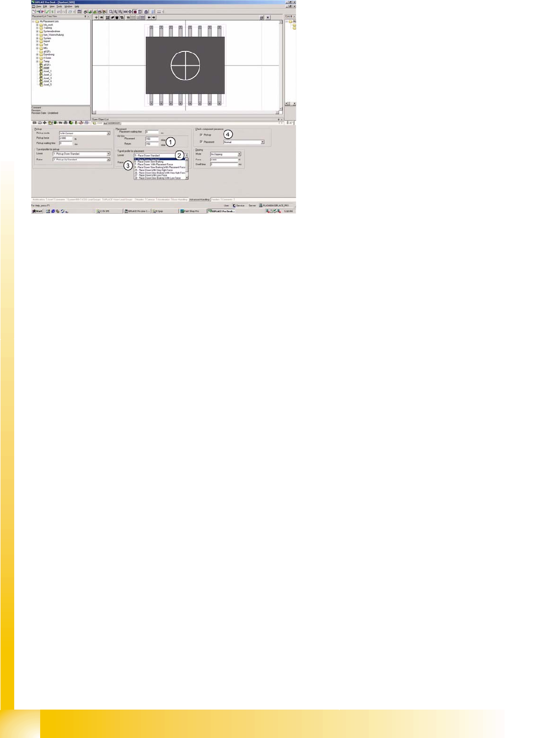
1. Air kiss programming:
– During placement with C&P20 or TWIN head. The value is regulated at the vacuum generator.
– During return to FM or reject conveyor with C&P20 or TWIN.
– For C&P6/12 heads: this value is used to control the air kiss time.
2. Velocity profile :
– (5) Place down, standard, with full speed and placement force of 2N in light barrier mode.
– (6) Place down, with slow braking, during last 1 mm of placement height.
– (7) Place down, with (increased) placement force (3 to 5 N) for C&P heads;…3 to 15 N for TWIN
head.
– (8) Place down, with slow braking and (increased) placement force (see above).
– (25) Place down, with very high placement force (future option).
– (26) Place down, with slow braking and very high placement force (see above).
– (27) Place down, with low placement force (1 N) at TWIN head.
– (28) Place down, with slow braking and low placement force (1 N) at TWIN head.
– (29) Place down, with very low placement force (no longer used).
– (30) Place down, with slow braking and very low placement force (not used).
– (31) Place down gently for TWIN (0201 profile).
3. Velocity profile :
– (9) - Place, up, standard, with full speed and no delay.
– (10)- Place, up, with slow start, to ensure that vacuum has been correctly released.
4. Component check:
– Normal - component check with vacuum (in case of C&P20 always with CO-Sensor).
– Advanced component presence check with component sensor & vacuum check combined
(C&P12)
– Component height.
– Component height - without vacuum.

SIPLACE Pro 3.0 Programming Interface for Component Shapes
Influencing SIPLACE Vision Through Specific Programming Handling Component Programming
Student Guide SIPLACE Vision (Customer)
Edition 12/2008 EN SIPLACE Pro 3.0 Programming Interface for Component Shapes
173
7.4.6 Influencing SIPLACE Vision Through Specific Programming
If the pickup tolerance is set too low in the component shape or component feeders, the Region of
Interest (ROI) will also be too small and the CO will be rejected during reversed pickup procedures.
As a result, pickup displacement in the X/Y position will also be too limited.
If a smaller pickup tolerance is programmed in the feeder than in the CS, the smaller tolerance value will
apply.
7.4.7 Import from Fiducials During LCU Import
Select the menu LCU Import Wizard under Tools.
7.4.8 Component Shape Data Download at Station
The CS download at the X-series stations shows the assignment of component shapes as a complete
data path, with the individual component shape names.
The CS download at the HF-/HS-/S-/F-series stations shows the assignment of component shapes as
an equivalent number.
SIPLACE Pro:
CO 1 is assigned to CS „System\2000“
CO 2 is assigned to CS „System\2000“
CS „System\2000“ with LC equivalent number. 10500
HS machine:
CO 1 is placed with CS name „10500“
X machine:
CO 2 is placed with CS name „System\2000“