SIPLACE Vision Customer_en.pdf - 第16页
Introduction Camera Overview Individual Camera Types - Details S tudent Guide SIPLACE V ision (Customer) Introduction Edition 12/2008 EN 16 3.4.1.4 CO Camera TWIN 'IC' SST 33 ('FC' SST 25) 3.4.1.5 PCB…
Introduction
Individual Camera Types - Details Camera Overview
Student Guide SIPLACE Vision (Customer)
Edition 12/2008 EN Introduction
15
3.4.1.2 CO Camera C&P12 SST 28
3.4.1.3 CO Camera C&P6 (C&P12 'HR') SST 29
Legend
1. Camera sensor
2. Lens system
3. 45° mirror system
4. Three programmable illumination levels
5. 0° illumination level programmable
Legend
1. Camera sensor
2. Lens system
3. 45° mirror system
4. Three programmable illumination levels
5. 0° illumination level programmable
Introduction
Camera Overview Individual Camera Types - Details
Student Guide SIPLACE Vision (Customer)
Introduction Edition 12/2008 EN
16
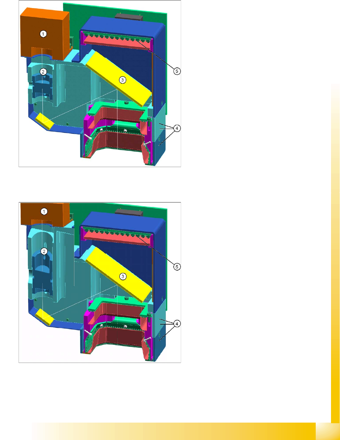
3.4.1.4 CO Camera TWIN 'IC' SST 33 ('FC' SST 25)
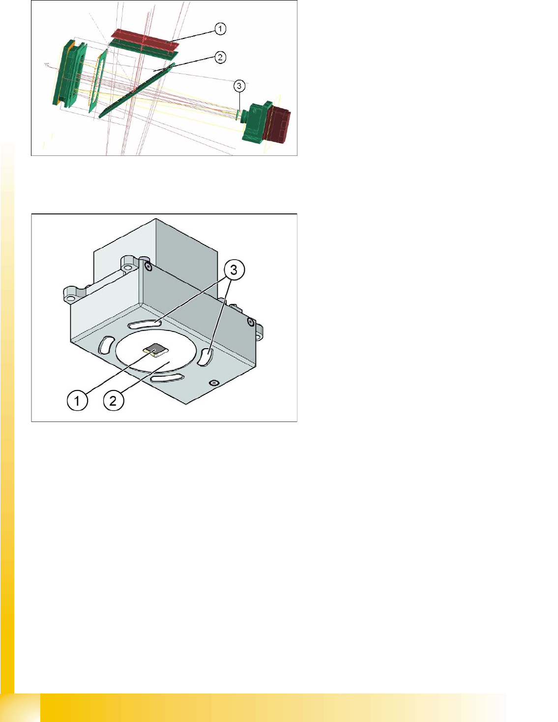
3.4.1.5 PCB Camera Standard SST34
Legend
1. 0° illumination
2. 45° mirror
3. Lens system with camera sensor;
further illumination levels near CO (left)
Legend
1. Direct red illumination
2. Diffuse red illumination
3. 4 openings for blue illumination at side
Introduction
Individual Camera Types - Details Camera Overview
Student Guide SIPLACE Vision (Customer)
Edition 12/2008 EN Introduction
17
3.4.1.6 PCB Camera SST 24
Optional PCB camera with multicolor illumination (often incorrectly known as multicolor camera)
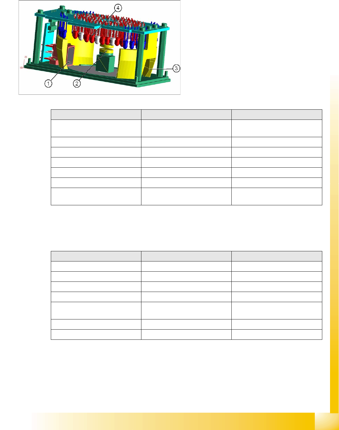
3.4.1.7 Coplanarity Sensors
Coplanarity sensors are available for ensuring that the placement quality remains at the highest possible
standard.
Legend
1. 0° direct illumination direction
2. Lens system
3. Optical fiber for blue
4. Diffuse white / IR illumination
5. Camera sensor here outside the image
Parameters PCB camera 24 PCB camera 34
Multicolor illumination for digital PCB
camera
YES No
SST 24 34
Resolution [µm] 12 12
Field of vision [mm²] 5.7 x 5.7 5.7 x 5.7
Min. fiducial size [mm²] ~ 0.3 x 0.3 ~ 0.3 x 0.3
Max. fiducial size [mm²] 3 x 3 3 x 3
Illumination colors] 5 White /IR diffuse white /IR steep /
blue
2 red/ blue
Parameters ILD 2200 IVP 3D coplan
Own computer No (station computer) Yes
SST 17 37
BGA recognition No Yes
Flux inspection No Yes, specially for BGA
Min. pitch [µm] Gullwing 0.4 µm Gullwing 500 / Lead width 300
BGA 800 / Ball ø 400
max. component size [mm] 50 x 50
Option for machines Fx / HF / HF3 / D1 / X2 / X3 X2 / X3