SIPLACE Vision Customer_en.pdf - 第110页
Component Shapes New SIPLACE Vision Functions for 605 and 701 Station SW SIPLACE Vision Flux Inspection – only in 605 SW S tudent Guide SIPLACE V ision (Customer) Component Shapes Edition 12/2008 EN 11 0 5.4.3 SIPLACE Vi…
Component Shapes
SIPLACE Vision Robustness Display New SIPLACE Vision Functions for 605 and 701 Station SW
Student Guide SIPLACE Vision (Customer)
Edition 12/2008 EN Component Shapes
109
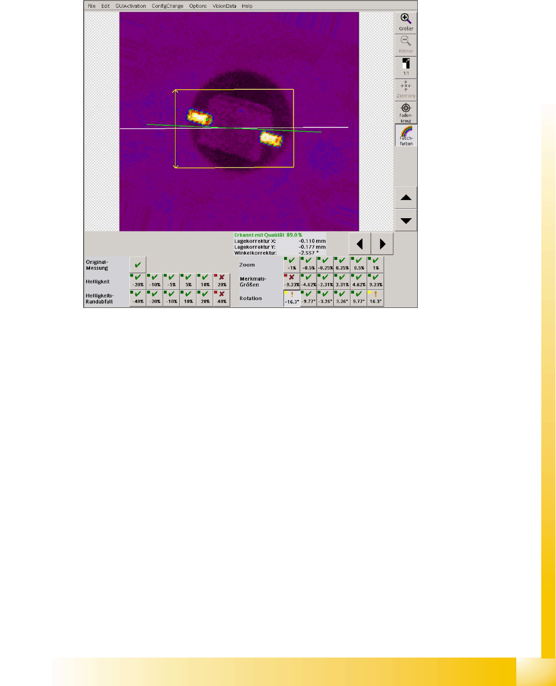
5.4.2.6 Rotation
In the following 6 measurement steps the component image is rotated electronically and a detection is
carried out. It is checked if the measurement methods can detect these rotated component images with
the existing algorithms or filters.
5-14: Angle measurement in the robustness test
The angle measurement fails in the fine angle measurement step if the camera image was rotated to
16°. The measurement returns a result which, however, doesn't reflect the actual angle position which
is near the programmed tolerance minimum.
Attention: A SOD323 component with this angle position would be incorrectly placed.

Component Shapes
New SIPLACE Vision Functions for 605 and 701 Station SW SIPLACE Vision Flux Inspection – only in 605 SW
Student Guide SIPLACE Vision (Customer)
Component Shapes Edition 12/2008 EN
110
5.4.3 SIPLACE Vision Flux Inspection – only in 605 SW
When placing BGAs, to which no solder paste can be applied, (e. g. POP = Package on Package) the
balls of the BGA must be coated with a flux or solder paste. To ensure a secure soldering, it is necessary
to check if the coating of the balls is sufficient. This check is carried out by the Vision system by means
of a flux inspection.
The inspection of the coating is combined with the position detection and the component inspection in
order to avoid an additional image to be taken and to save time. The flux inspection is carried out after
the normal optical component centering steps.
The inspection of the coating makes special demands to the flux. Usually the flux is transparent in the
applied layer thicknesses. For this reason pigments must be added to the flux to ensure that the system
can recognize if the balls are sufficiently coated.
Flux inspection can only be used in conjunction with the 605 SW because it is not possible to place
Linear Dipping Units (LDU) on a SIPLACE X41.
Other X machines can house the LDU (on X feeder tables) or the hitherto existing flux dipping unit with
DIP turntable (on S tables). In SIPLACE Vision from version 351.15 onwards, intended for SC SW 605,
the dipped contacts can be optically centered after being picked up. The "Dipping before Vision" function
is not available in previous SW versions.
Two modes are available for a combination of flux dipping and optical recognition:
Vision Dipping
Dipping Vision
From station SW 605 onwards generally all component shape types with Vision before dipping can
absorb flux at the electrical contacts which is already possible with the 50X SW and the hitherto existing
flux dipping units.
For a 3D coplanarity inspection of a BGA Vision before dipping must be selected since the ball heights
change unpredictably during dipping, thus causing all coplanarity measurements of dipped BGAs to fail.
In this workflow, however, the centered component could be moved on the nozzle during dipping.
The dipping before Vision function can only be used for BGAs (CCGA) and the special nonstandard,
connector and socket types, thus for ball connections only.
Using dipping before Vision the flux is applied to component in the dipping unit after the component is
being picked up.
5.4.3.1 Flux Inspection
In this inspection step a visual check is performed in order to find out if the contacts are coated with flux
or solder paste.
Requirements and General Information
The following requirements must be met in order to use this option:
The Dipping option must be selected for the component.
The required sequence of the function must be programmed for the component shape.
With Dipping before Vision it is not possible to determine the amount of applied flux or solder on the
contacts! (E. g. in order to detect if the solder paste causes short circuits.)
Possible causes for insufficient coating of flux or solder paste:
Damage to the balls
Surface properties of the balls (e. g. dirt that hampers a coating)
Inappropriate flux (The flux is transparent and does not change the optical appearance of the balls.
The flux must be white or darkly pigmented.)
Height of the flux in the dipping unit too small
Component Shapes
SIPLACE Vision Flux Inspection – only in 605 SW New SIPLACE Vision Functions for 605 and 701 Station SW
Student Guide SIPLACE Vision (Customer)
Edition 12/2008 EN Component Shapes
111
BGA not completely dipped into the flux
Component poorly positioned on the nozzle
Component and dipping unit not aligned in parallel.
Dipping time too short
Optical Appearance
Blue pigmented fluxes and gray solder pastes have a similar optical appearance.
If BGA contacts are dipped with the layer thicknesses being too thin they look almost like undipped
BGAs.
Aged components with oxidized contacts also influence the optical appearance. These contacts are
coated worse with flux or solder paste so that the optical appearance is similar to an un-dipped
component in the camera image.
Of course these contacts are also extremely difficult to solder, but soldering is not the aim of this
inspection step!
Component Shape - Test Procedure
3 operating modes have been created in order to prepare components completely for the test:
No dipping of the component and no flux inspection
No dipping of the component but carrying out a flux inspection
Dipping the component and carrying out a flux inspection
Thus, it is possible to test the component completely in both states in the optical centering. That means,
that complete position measurement and BGA contact inspection is also possible.
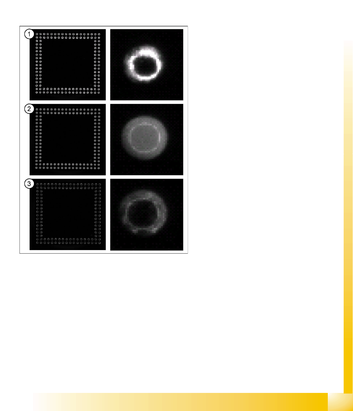
Legend
1. Component undipped:
BGA and ball without flux
A ball can be seen as a bright ring. This ring is
very bright and the center is very dark; the
image is very rich in contrast.
2. Component dipped; flux with white pigments
BGA and ball with white flux
A ball can be seen as a bright ring with an even
brightness to a large extent. The center is
similarly bright as the outer area and the
contrasts are low.
3. Component dipped; flux with dark (blue)
pigments
BGA and ball with dark (blue pigmented) flux.
A ball can still be seen as ring, but
considerably darker as for the undipped ball.
Because of the diversity of fluxes it is necessary to
have the optical appearances of dipped and
undipped checked by Siemens (at least by means
of the SIPLACE Vision log files).