SIPLACE Vision Customer_en.pdf - 第192页
Appendix S tudent Guide SIPLACE V ision (Customer) Appendix Edition 12/2008 EN 176
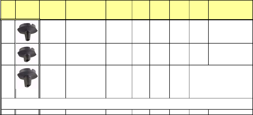
Nozzle
type picture
order nr.
(version nr.
may change)
Material / Used for..
(sample dimension.)
min. comp.
dimension
(in mm)
nozzle
length
(in mm)
compone
nt sensor
all comp.
vacuum
difference
(in mbar)
Nozzle
scanning
SipVision
Comp height
min./max defined by
R&D dep.(in mm)
1133 03014336-
Evoprene
Tantal 3.2x1.6A/B /
1206 2.8x1.2
9.4
q
100
0,5 - 2
1135 03015384-
Evoprene
Tantal C/D 3.0x1.4
7.4
q
110
3,0 - 4
1235 03015222-
Evoprene
4.5x3.2x1.6 until
5.7x5.0x1.7 (calib.
Part / ultra thin
components.) 3.0x1.4
9.4
q
110
0-2 (Please Note: approxim.
0.5mm higher component at this
nozzle interrupt the LASER
beam of the Comp. Sensor when
the Z-Axis is at top position.)
Component-Sensor works for all components up to specified maximum comp. height of 4mm.
Machine execute a vacuum check at reference run; but do not check comp. Presence with vacuum check.
Edition 5.0 print 18.11.2008 nozzle overview_cu_D_E.xls C&P20 Nozzle param Siemens Ind.Sec. DT EA CS E

Appendix
Student Guide SIPLACE Vision (Customer)
Appendix Edition 12/2008 EN
176
linienfarbe 192,26,128
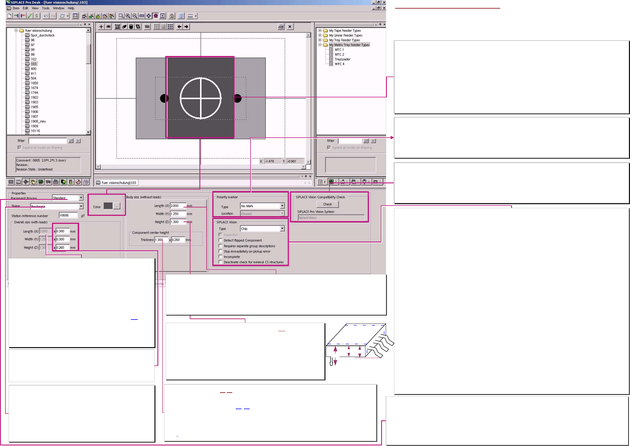
Overall size with leads (component dimensions WITH pin's)
The comp. dimensions X/Y/Z without pin's & the PIN dimensions in all
groups are respectively added and the result is displayed here.
With SIPLACE Pro 5.1 this 3 values are separated for SIPLACE Vision
& ICOS.
** This allow to separate ICOS-special programmings from
the calculated real dimensions for SIPLACE Vision.
X/Y-value equal to X/Y without PINs for CHIP/MELF. or
X/Y-value for comp. with PIN = ∑ (PINgruop offset * PIN-Length/2 ) of
the respective, opposite pin-groups
The height of the centering pins is added to the body height (3).
From this calculated Z dimension is the target position for the Z-Axis
positioning defined for: pickup height (lin.feeder...); optical centering
(stationary cameras); placement height & for AOI inspection system.
(for the height of the centering pins the Z-axis should move slowly).
Component body shape
The comp. body shape is a classification feature of different component
shape types.
From the horizontal cylinder of a MELF the kind of illumination and the
measurement method for comp. width measurement reduced.
The vertical cylinder of the ECV’s set no special illumination or
measurement.
The standard body is rectangular and is selected also if the real body
(of e.g. a shield is an Polygon.
Properties (placement methods)
This setting checks the specified, special handling methods of the comp. shape type. (at Integrity check
√ or at
producability test of the download). This functionaltiy could be reached also with single setting of profile and comp.
checks in the respective menus,
Standard: comp. Is picked with contact and is placed with maximum speed.
0201 (0603mm): is picked contactless (profile 17) and with comp sensor is the presence tested.
01005 (0402mm): is picked contactless (profile 35) / with comp sensor is the presence tested and with reduced force
placed profile 33 or 34 set this. / C&P12 with restrictions and special sleeve / feeder ).
Programming windows of comp. dimension tolerances X/Y/Z
This comp. dimension tolerances define the possibility to
recognize wrong picked comp.’s optically and sort them OUT!
Tiny, proper tolerances are (especially at comp. width of CHIP &
com. length) necessary for YOUR increased placement reliability.
Component dimensions Z WITHOUT (Centering) pin's (2)
This comp. dimension Z is the comp. height without centering pins but
electrical terminals are included in this height value
because of focus height & dynamic profiles entered in other editor windows!
!30% of this height value (given by C height and R on nozzle) is the minimum
limit for the comp. sensor at C&P20-head for component presence check (at
the moment (up to 701) programming error workaround).
Calculation for the height with pin -centering pins- see left.
Body dimensions (component dimensions X/Y WITHOUT pin’s)
The comp. dimensions X in horizontal direction is the direction in which (normally) the nozzle is set.
Y direction is the vertical component direction (normally the shorter one).
At teaching with SIPLACE Vision camera support this X/Y-Data may include the Pinlength round the plastic
body (body is the outline arround the visible bright parts if programmer set nothing different).
This depent on the programming of the operator on the end to the Comp. shape-assistent teach sequence.
Component center height (1)/(2) This field must not have a 0 value in future!
>This is the body height of the component normally identical to the height ‚without Pin’s.
Electrical terminals (Gullwing/J-Lead/Wraparound) on the side or Balls/ columns are included.
>The tolerance is defined that way (2)
-(1)that a measurement between this pin's is accepted too.
Used is this value for comp. height check at the comp. sensor of C&P20 head and the C&P12head and
for the comp. presence check of the comp. sensor from C&P12 head.
For a component with centering pins or with coloumns program the comp. sensor only for presence
check!
SIPLACE Vision Data window (contents not transferred to ICOS machines)
Type
One of the 17 possible component shape types have to be selected before Download to the SIPLACE Vision
machines! Component shapes at ICOS machines do not need this classification.
BareDie; Chip; Melf; Moulded; ECV; SOxx; QFP; DPACK; SOT; SOJ; PLCC; BGA; CCGA; Socket; connector;
Shield; Nonstandard. With defined type & with ’Incomplete’ the comp. shape geometry could be taught w. comp.
camera.
❑ Inspection
The inspection mode is always active (also when it is insensitive OFF). With Nonstandard, Moulded, BGA and
CCGA comp. shape types the programmer could disable this mode !NOT recommended!.
❑ Detect flipped Components
Resistors in CHIP spape type could be recognized in their Z-orientation. Low grade solder connections caused by
paint or slopes are avoided.
❑ Requires separate Group description
This is necessary for terminals like: corners; polygon circles, columns and blops because at ICOS are no proper
measurement algorithms therefore available (error message at producability test or download).
Necessary also for bright terminals on bright background which mighty be recognized by the better cameras of
SIPLACE Vision.
Another use is for BGA’s with desired inspection for a lot of terminals (at ICOS often only the outer terminal ring is
inspected because of excessive time consumption)
❑ Stop immediately at pickup error
Thisis to activate at tantal capacitors that the component could be removed from the operator. (This avoid sparking
if the component would be cut).
❑ Incomplete
With this in complete comp. shape description could be downloaded to SIPLACE Vision machines to teach them
with the comp. camera.
(program comp. Dimensions /-tolerances and SIPLACE Vision comp. shape types).
❑ Deactivate check for minimal CS structures
necessary to place components with very tiny terminal features in ’prototype numbers’.
comp. features which are to tiny for the comp. camera resolution and for the precision specification are not
anymore checked at download to the station (and they could be placed ).
Take placement accuracy restriction in account !
Polarity marking
For a marking of PCB- and set up printouts, to see components with polarity better. (Helpful also to color the body
of such components (e.g. red).
Marking type: Line or dot
Marking location: (may cover connecting features)
Body color
For marking comp. shapes for PCB printouts to recognize special comp.’s for visual inspection better.
Helpful e.g.
Red comp.’s with polarity
Blue comp.’s with separate group description
Orange comp.’s with Precedence’s
Yellow comp. for high resolution camera or 3D-Coplanarity
Green real BareDie -take care on ESD safe Die Handling-
Lila comp. programming with not recommended features or with disabled ‚min. structure check.
Light blue Resistors
Rosa Coil
Brown Tantal. ...
SIPLACE Vision Compatibility check
testing functional extensions in SIPLACEVision recognition SW.
❑ SIPLACE Vision V33 (since SR/MC 603) is the required extension for:
► comp. Shape description incomplete
► Deactivate check for small component shape structures
Component shape body data
** since SIPLACE Pro 5.1 the X/Y-Z-body dimensions for SIPLACE
Vision are calculated (incl. Centering pin height) and separatelly
from this dimensions for ICOS also respectivelly they are entered.
1
2
3
A programing overview about process reliability Editon for SIPLACE Pro 5.0 extended for 5.2