SIPLACE Vision Customer_en.pdf - 第41页
Component Shapes Component Centering with Combined Usage of SIPLACE Vision and ICOS Structure of Component Shape Data S tudent Guide SIPLACE Vision (Customer) Edition 12/2008 EN Component Shapes 41 The following data a…
Component Shapes
Structure of Component Shape Data Component Centering with Combined Usage of SIPLACE Vision and ICOS
Student Guide SIPLACE Vision (Customer)
Component Shapes Edition 12/2008 EN
40
5.1.1 Component Centering with Combined Usage of SIPLACE Vision and ICOS
When using both Vision systems (ICOS and SIPLACE Vision) for component centering, you can select
either a common or a separate dataset for each CS number, in SIPLACE Pro. Separate datasets also
require separate maintenance. Only use this option, if you expect that geometric data which have been
taught for SIPLACE Vision will have a negative effect on the optical recognition in the ICOS system of
older machines.
Data management is as follows:
SIPLACE Vision processes the exact component shape dimension descriptions and can then alter these
through teaching. However, this may lead to recognition problems for some CS descriptions, when used
in ICOS Vision systems.
In these cases, it is advisable to keep the group data and lead data descriptions separately in SIPLACE
Pro.
This alternative option - separate data management - must be selected before you download to
SIPLACE Vision!
In rare exceptions, it may become necessary to create a completely new CS dataset for SIPLACE Vision,
if the SIPLACE Vision and ICOS descriptions are incompatible.
This could occur with various Moulded CSs (which have identical dimensions for ICOS), due to the
colored body and with various CSs, which have identical X/Y dimensions but different Z CO heights for
the CO sensor (in SIPLACE Vision).
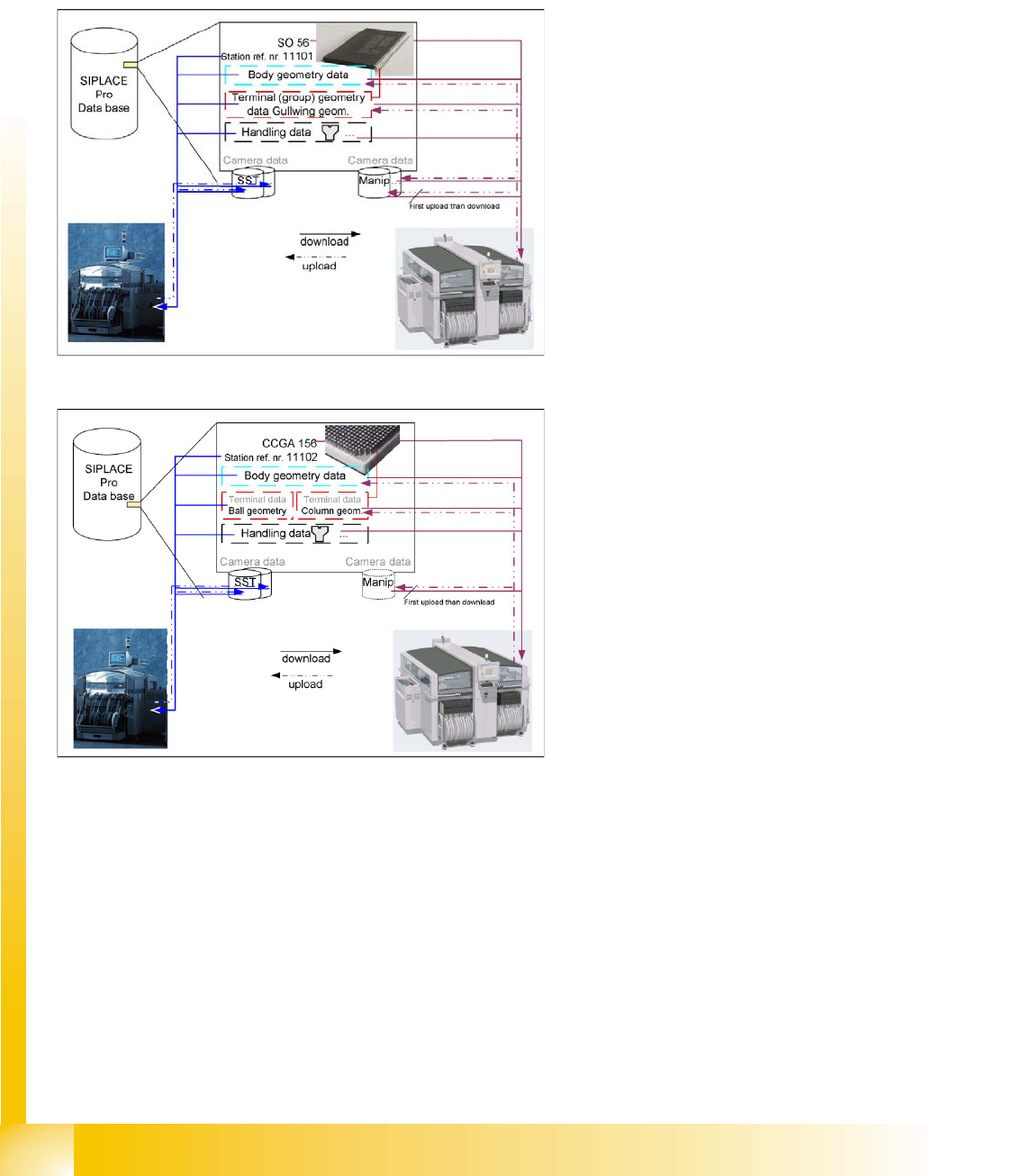
The older ICOS image processing system
saves all teaching data in the SST file of the
relevant sensor type. The CS download data
consists of general data, group and lead
descriptions and the teaching data from the sensor
system type data area.
The SIPLACE Vision image processing system
saves the teaching data in a general data area; in
the group and lead descriptions and in the
manipulation data.
The CS download data consists of general data,
group and lead descriptions and the teaching data
from the manipulation data area.
Enabling the component shape default values,
resets the data to its default values (manipulation
data).

Component Shapes
Component Centering with Combined Usage of SIPLACE Vision and ICOS Structure of Component Shape Data
Student Guide SIPLACE Vision (Customer)
Edition 12/2008 EN Component Shapes
41
The following data are always managed together for the different Vision systems:
– CS body type
– Station reference number – if this has been programmed in the plain text name
– CS body height Without leads for CO sensor;
– Calculated overall body size (with leads), – for determining the first theoretical pick and place
height.
– 0201 CO processing details are also provided.
The following data are always managed separately for the different Vision systems:
– CO type e.g. Melf, QFP,...
– Inspection mode
– Detect flipped components (for ICOS in SST file)
– Requires separate group description
– Stop immediately at pick up error.
Data for SIPLACE Vision are divided up as follows:
– Geometric data are stored in the body or lead geometrics on the SIPLACE Pro computer
– Illumination and algorithm changes are stored in the manipulation datasets.
Recognition of teaching datasets is possible with insensitive image display or can be deleted.
– SST teach data for the ICOS system are displayed in the Vision Data Manager (VDM as
insensitive
– Manipulation data can indirectly recognized because the camera, for which teaching is
performed, is listed in the VDM.
Processing data may include:
– Nozzles and camera for the placement head
– Feeders for component availability
– Processing information for pickup and placement
– Acceleration settings for individual axes
– Programming interface data include data such as:
– Body color – for display in the editor and on the boards
– Nozzle contact surface dimensions for optical display of the applicability
– The X/Y body dimensions
– Pin 1 detection

Component Shapes
Structure of Component Shape Data Overview of Component Shapes Which Require Separate Group Descriptions
Student Guide SIPLACE Vision (Customer)
Component Shapes Edition 12/2008 EN
42
5.1.2 Overview of Component Shapes Which Require Separate Group Descriptions
CS type name Lead groups- separation
required?
Reason
Shield Required without exception,
due to new algorithms
SIPLACE Vision uses corner recognition or polygon circle
recognition. ICOS uses virtual leads or ball descriptions.
CCGA Not important SIPLACE Vision recognizes column leads. ICOS processes
these components as BGAs.
BGA and
CCGA
Possibly required If (to save time) not all leads have been activated or programmed
for the inspection mode (for ICOS).
Plug Possibly required SIPLACE Vision permits all types of leads. ICOS does not allow
any combination of leads.
Nonstandard Possibly required SIPLACE Vision can center lead types which would need to be
omitted for ICOS e.g. lead-ball combinations etc.; BLOP leads;
leads with notches or rounded corners.
BareDie Possibly required if the PDC
description for ICOS needs to
be used.
Chip COs were described without leads (PDC).
Where possible, replace all lead-less descriptions!
(Use as regular FDC in LC for ICOS.)
Components
with special
descriptions for
ICOS
Important e.g. 2 pin diodes (SOD 323) need to be processed with a chip or
BGA description in ICOS, so that COs which are picked up from
the side can be sorted out.
For component shapes with lead feature combinations for
SIPLACE Vision.
All COs with
white bodies
and metallic
leads on them
Important, if SIPLACE Vision
is to recognize these features.
White CO bodies must be programmed as white bodies (often as
CHIP with virtual leads on the narrow sides) in ICOS. Due to
improved camera illumination technology, SIPLACE Vision now
supports the recognition of metal surfaces on a white
background.