SIPLACE Vision Customer_en.pdf - 第52页
Component Shapes Specific Component Shapes CHIP Component Shape S tudent Guide SIPLACE V ision (Customer) Component Shapes Edition 12/2008 EN 52 Special features The inspection mode is se t as a defa ult. This ca n not…
Component Shapes
CHIP Component Shape Specific Component Shapes
Student Guide SIPLACE Vision (Customer)
Edition 12/2008 EN Component Shapes
51
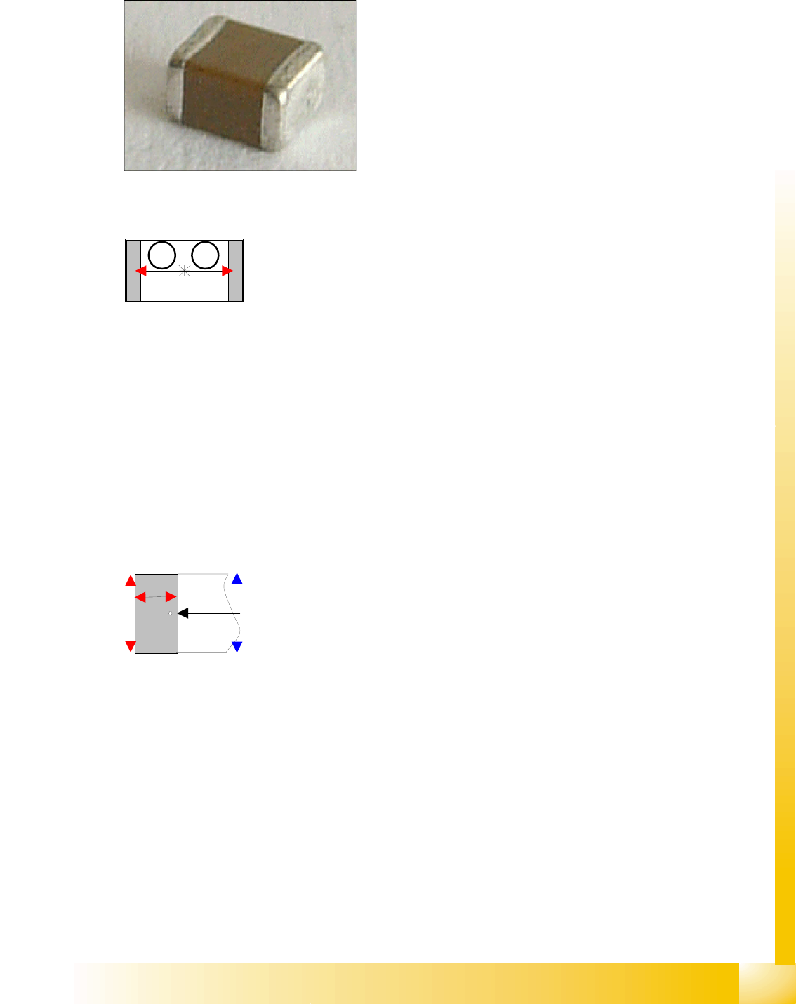
5.3.3 CHIP Component Shape
JEDEC description
JEDEC description
Lead description
Body description: rectangular.
The Z height of the body determines the measurable height
in the CO sensors.
The X/Y body dimensions determine the field of vision, the
Region of Interest.
This also determines the outer starting edge of the
Wraparound leads.
This component consists of two lead groups, each with one
lead.
The leads in the two groups must be identical! This
restriction no longer applies with SC 702 (although you do
need to switch over to "separate group descriptions" for
ICOS –SIPLACE Vision).
The leads are inside the body surface.
In the case of this component, the leads are understood to
begin where the body begins, meaning that a group offset
does not need to be programmed.
After optical centering, the distance between the leads and
the center (body center) is measured and used for the
placement coordinates.
Left: pin begins here
Right : pin ends here*
Vertical red arrow: lead width
This component shape has so-called Wraparound leads,
which are wrapped around the component body, hence the
name Wraparound.
This defines the default lead direction: towards the CO
center (correct for Tantals (Moulded), reprogram if
necessary);
The lead description also includes the lead length and
width.
The leads are as wide as the overall body (if the leads are
narrower than the body, the CO is classified as Moulded).
The lead length must not exceed 50 percent of the body
length
No notches may be programmed.
*The pin end is shown by a point in the results diagram.
1 2
Component Shapes
Specific Component Shapes CHIP Component Shape
Student Guide SIPLACE Vision (Customer)
Component Shapes Edition 12/2008 EN
52
Special features
The inspection mode is set as a default. This can not be changed, since the body dimensions also
need to be measured (Body Dimension Check), to avoid vertical placement due to upright/sideways
pickup. The body description tolerances should therefore be kept sufficiently low.
Joint datasets with ICOS data possible:In ICOS descriptions, a CO dimension check is only performed
if the lead width matches the body width. Check the tolerance values and reduce if necessary. CHIP
components, which have been programmed as PDC, can not be automatically assigned. In this case,
you will need to reprogram the CS with the leads.
Due to the very simple programming method, involving body size with attached wraparound leads, NO
component shape wizard is offered for CHIP component shapes.
SW extension: Lead length inspection can be programmed and used for CHIP component shapes from
SC 702.
Recognition of flipped components
A flipped CHIP component can be recognized with the so-called Face Down method and placement
of it then omitted, if this option is enabled in the CS programming function of SIPLACE Pro. Unless
you want to check all COs under this component shape for this pickup error, create an additional CS,
which can be selected for this option.
Recognition of flipped COs can be enabled or disabled in the geometry data menu. When using
ICOS systems, this option is trained at the station and the results stored in the SST camera file.
ICOS and SIPLACE Vision use the same measurement principles for this option.
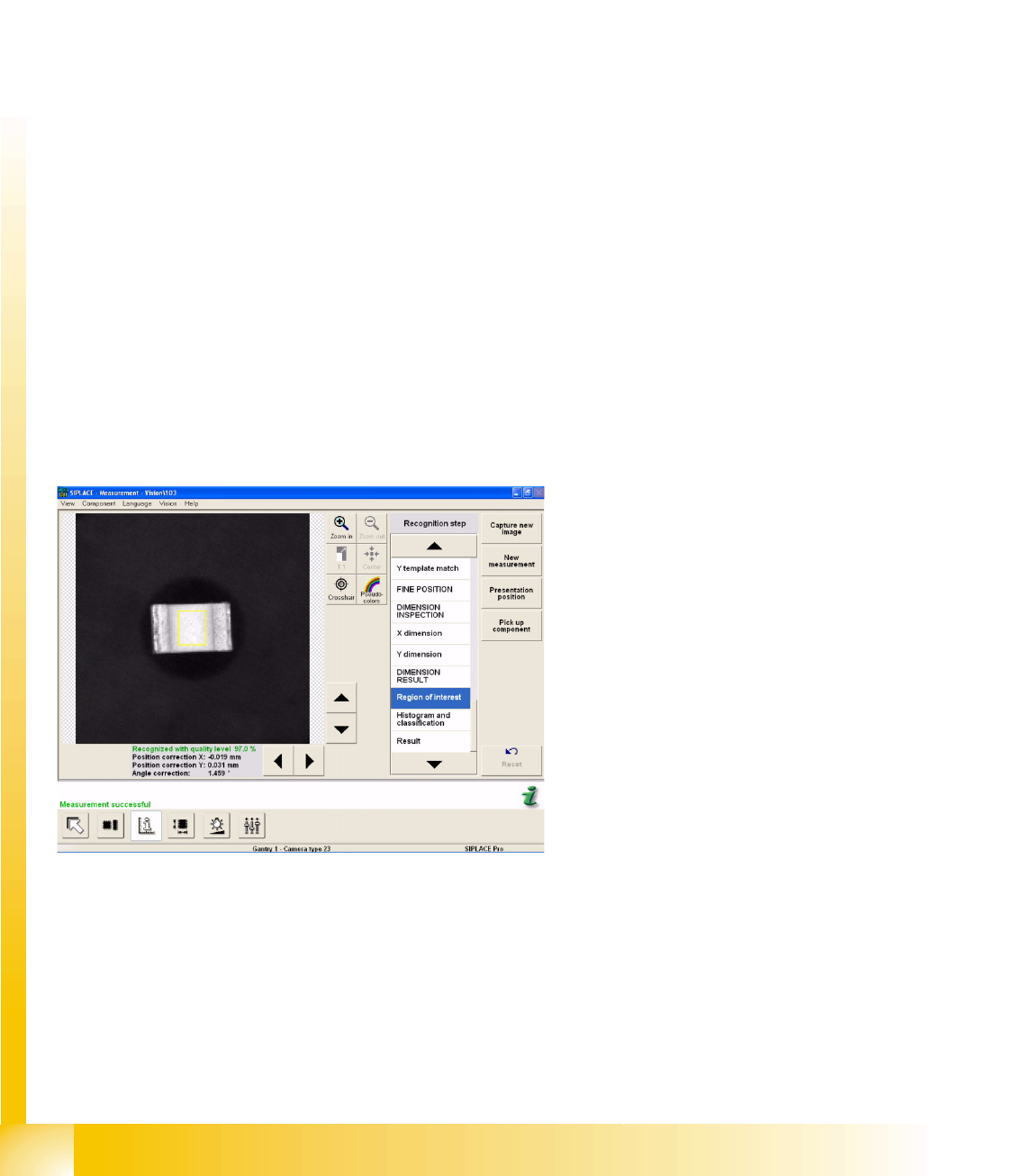
An additional measurement window is created around the center of the CHIP CO (Region of Interest,
for flipped recognition). Inside this window, all the brightness values greater than 127 will be
interpreted as CO bottom side (additional evaluation steps cover generation of a histogram and
classification). The brightness values below 127 are then interpreted as CO top side.
Example A:
CHIP component is correctly positioned at the
nozzle; during the recognition step Region of
Interest.
Component Shapes
CHIP Component Shape Specific Component Shapes
Student Guide SIPLACE Vision (Customer)
Edition 12/2008 EN Component Shapes
53
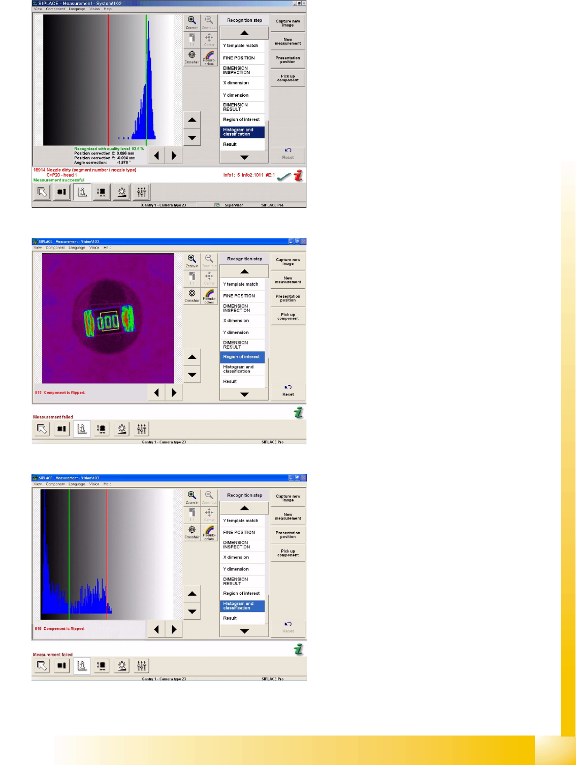
About Example A:
CHIP component is correctly positioned at the
nozzle; histogram and classification steps are
performed. The diagram shows the brightness
histogram i.e. the number of gray/white pixels.
Example B:
CHIP component is flipped and positioned at the
nozzle, during the recognition step Region of
Interest.
About Example B:
CHIP component is correctly positioned at the
nozzle; histogram and classification steps are
performed. The diagram shows the brightness
histogram of the CO label.