SIPLACE Vision Customer_en.pdf - 第63页
Component Shapes Optical Recognition and Evaluation of Un leaded COs Specific Component Shapes S tudent Guide SIPLACE Vision (Customer) Edition 12/2008 EN Component Shapes 63 Y dimension measurement step The brightness g…
Component Shapes
Specific Component Shapes Optical Recognition and Evaluation of Unleaded COs
Student Guide SIPLACE Vision (Customer)
Component Shapes Edition 12/2008 EN
62
5.3.6.2 Dimension Check for Unleaded Components
Dimension check recognition step
A CO dimension check is always performed on the
fine position determined for unleaded COs.
Firstly, the green angle is used to indicate the CO
center of the fine position.
The light blue frame shows the programmed CO
dimension.
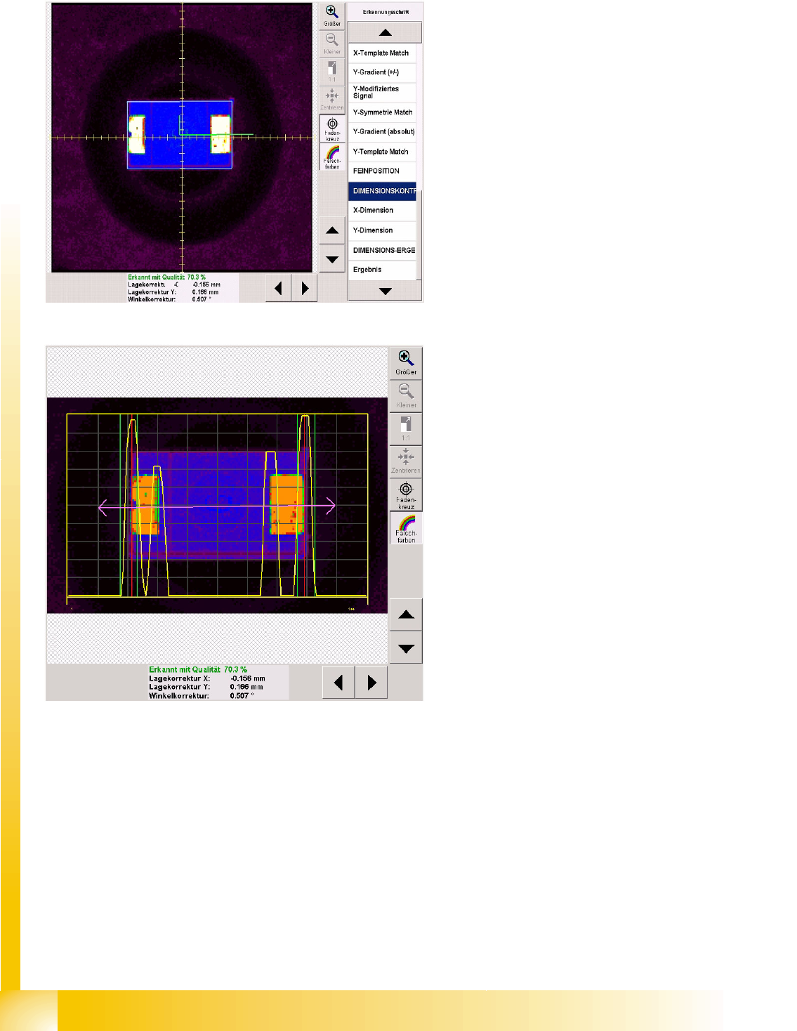
X dimension measurement step
The brightness gradients are determined for the X
direction.
The purple double arrow shows the CO length
with length tolerance, for which the yellow
gradient signal has been defined.
High gradients are interpreted as the beginning of
the CO and lower gradients as the lead end.
The vertical green lines on each side of the CO
show the tolerance field which the CO edge must
be within.
The vertical red lines show the detected CO
outer edge.
The dimension tolerance values should be set as
low as possible, to avoid upright placement.
Component Shapes
Optical Recognition and Evaluation of Unleaded COs Specific Component Shapes
Student Guide SIPLACE Vision (Customer)
Edition 12/2008 EN Component Shapes
63
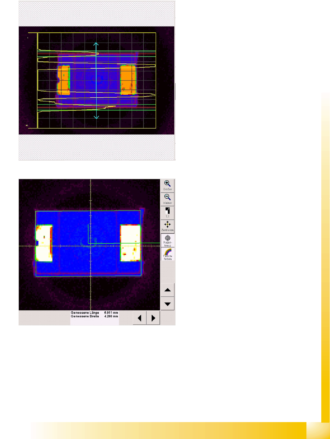
Y dimension measurement step
The brightness gradients are determined for the Y
direction.
The light blue double arrow shows the CO width
and width tolerance. The gradient signal for the
CO width is displayed in yellow.
Lower gradients indicate the CO outer edge (due
to dark body). If these are high enough, the outer
edge of the body can be determined. If not, the
high gradients for the lead side are used to
determine the alternative body width Y of the
Moulded CO.
The horizontal green lines on each side of the
CO show the tolerance field which the CO edge (or
lead side) must be within.
The horizontal red lines show the detected CO
outer edge.
Measurement window showing Dimension
result recognition step
The dimension rectangle for the determined CO
length (X) and width (Y) is displayed in green in the
CO fine position and fine angle.
At the edge of the rectangle shown, you can
clearly see the pseudo-color image, with the
injection edge of the Tantal capacitors (Moulded
COs).
The dimension check result is only shown here, in
the dimension result step.
Component Shapes
Specific Component Shapes Optical Recognition and Evaluation of Unleaded COs
Student Guide SIPLACE Vision (Customer)
Component Shapes Edition 12/2008 EN
64
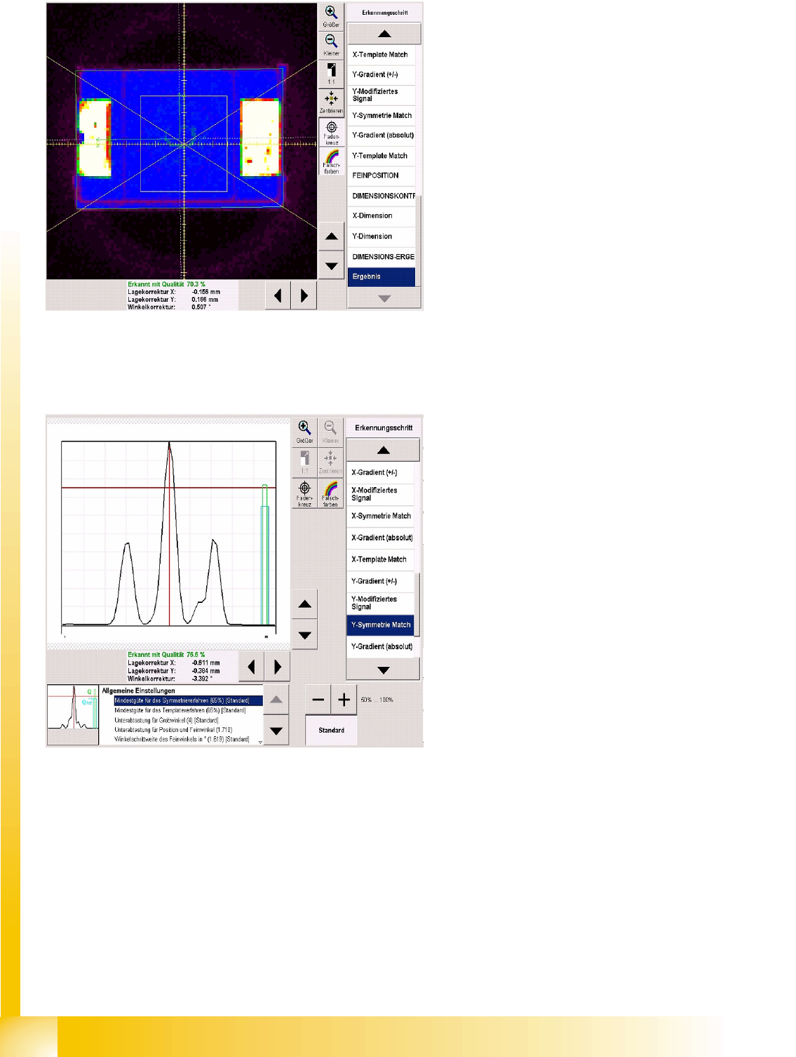
5.3.6.3 Algorithm Values
These settings do not normally need to be changed.
Diagram centering result
The diagram shows the following:
CS X/Y orientation: green angle in CO center.
CO center recognized for placement: white
dotted line.
Permitted CO angle tolerance: diagonal
yellow lines in CO camera center.
Since the results display is so important, it was
already shown during the intermediate centering
steps. If an error occurs, this will also be displayed,
so you can make the necessary adjustments.
The minimum thresholds for various measurement
steps can be altered here.
The relevant threshold and measurement value
bars will then be redrawn in the recognition step
diagram.
If the quality values for the symmetry procedure
are not achieved, centering will be performed with
the template method.
Sub sampling coarse/fine angle: gathers
several points of the image together, to form one
evaluation point.
Attention: The predefined recognition menus will
change when you switch over threshold values!