SIPLACE Vision Customer_en.pdf - 第168页
SIPLACE Pro 3.0 Programming Interface for Componen t Shapes Handling Component Programming Pickup Po sition Tolerance and Nozzle Assignment S tudent Guide SIPLACE V ision (Customer) SIPLACE Pro 3.0 Programming Interface …
SIPLACE Pro 3.0 Programming Interface for Component Shapes
Vision Data Manager Handling Component Programming
Student Guide SIPLACE Vision (Customer)
Edition 12/2008 EN SIPLACE Pro 3.0 Programming Interface for Component Shapes
167
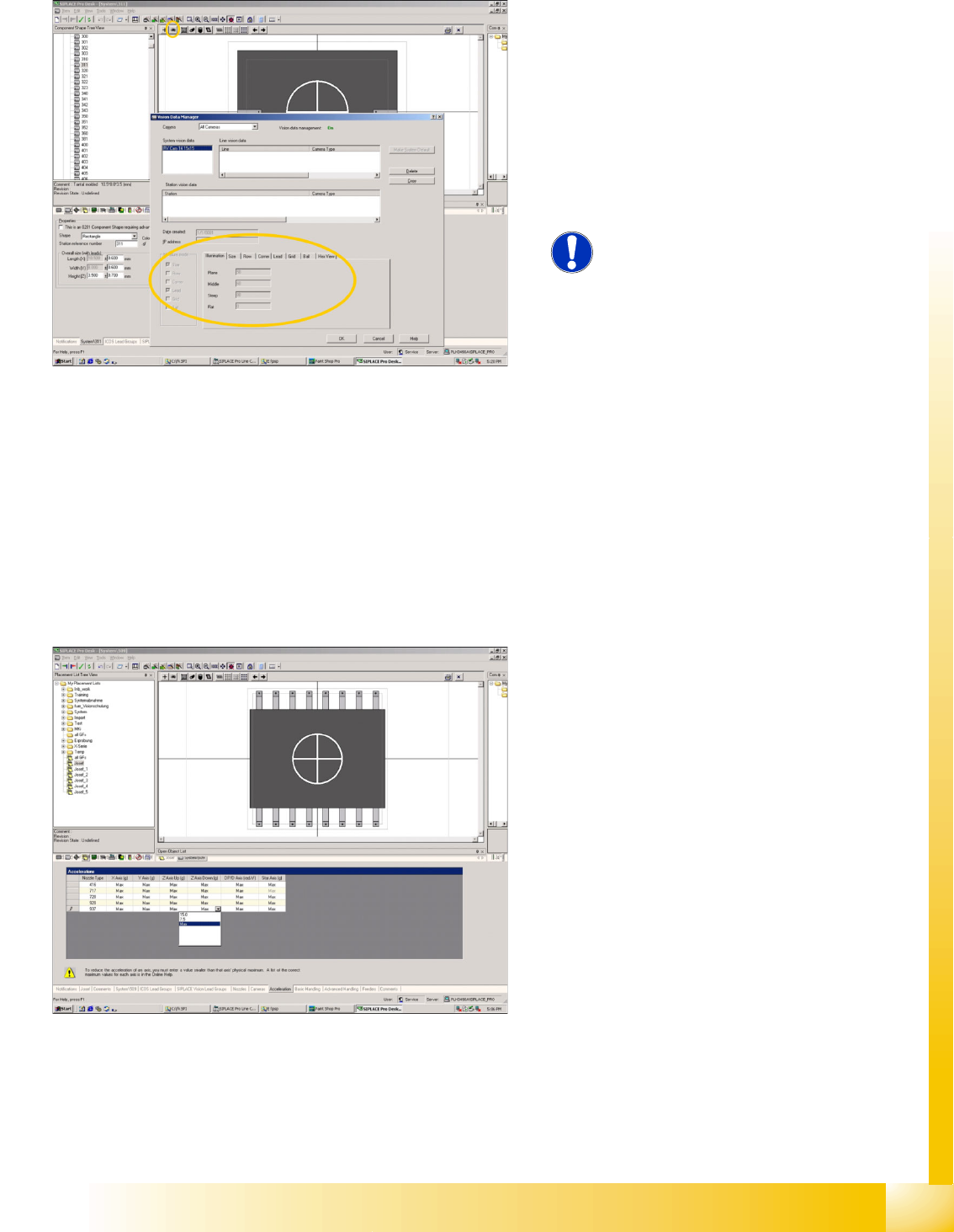
7.3.5 Vision Data Manager
7.4 Handling Component Programming
The Vision Data Manager (VDM) enables you to
check the component shape teaching data. This
can also be performed when the Vision Manager
(full) function is disabled (Vision Management is
switched to ON in screen dump).
Click on the eye symbol to view the teaching data
for a particular camera type. Select the required
Camera to view the insensitive data for the ICOS
measurement methods and camera illumination.
NOTE: When importing the CS data,
always import the SST files!
Experience shows that this is often
forgotten, although this is very
important.
If leads have been programmed for this
component shape, although the lead
measurement mode is disabled in the SST file, it
can be assumed that a programming trick was
used in ICOS. Nonstandard programming
methods such as these might well have a negative
affect on the SIPLACE Vision centering
procedure.
The acceleration of the selected axis refers to the
fastest machine type. Maximum therefore means
that the fastest axis speed for that machine type is
permitted.
If the acceleration is reduced, this will ONLY
reduce the acceleration value and will not initiate a
special processing mode*.
* In the SR/MC 4XX.xx Sw, reduced acceleration
programs slower initial Z-axis upwards travel.
SIPLACE Pro 3.0 Programming Interface for Component Shapes
Handling Component Programming Pickup Position Tolerance and Nozzle Assignment
Student Guide SIPLACE Vision (Customer)
SIPLACE Pro 3.0 Programming Interface for Component Shapes Edition 12/2008 EN
168
7.4.1 Pickup Position Tolerance and Nozzle Assignment
It is important for pickup position tolerance to determine how the size of the nozzle contact surface and
the component surface match one another. Nozzle programming and pickup position tolerance are
therefore explained in this section.
7.4.1.1 Pickup Position Tolerance
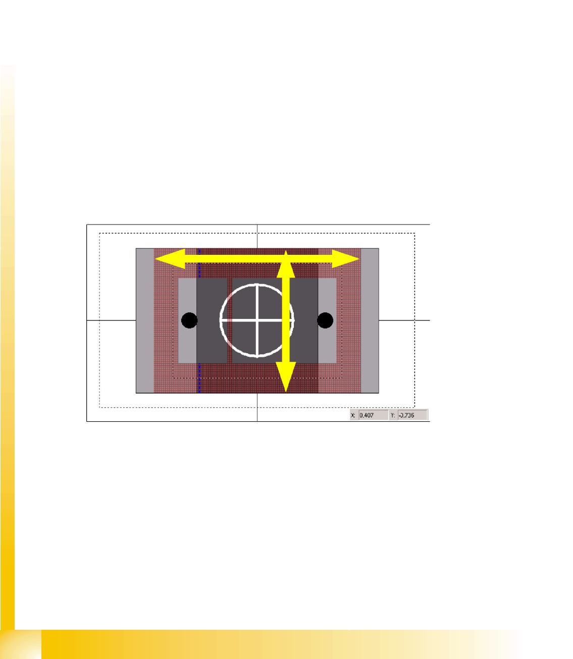
The pickup position tolerance standard values are derived from the size of the component shape.
When programming the real pickup position tolerance in your placement process, a differentiation is
made between 2 'types'.
CS dimension significantly larger than the nozzle tip
Due to high tolerance values for nozzle putdown, neither a placement nor a vacuum error can occur.
This means that the full position tolerance, calculated from the component tolerance in the feeder or tape
pocket, can be programmed here.
CS dimension similar or smaller than the nozzle tip
Due to low tolerance values for nozzle putdown, you need to take the placement pitch on the PCB into
account.
If high pickup tolerances cause the nozzle to reach considerably over the side edge of the component,
this could cause the nozzle to touch the neighboring component and change it at the moment of
placement. Observe the component pitches set in the PCB layout!
It is therefore recommendable to program a pickup tolerance which is roughly the same as the thickness
of the nozzle or just the value of the component edge pitch during placement.
To estimate the thickness of the nozzle, use the X/Y coordinates of the mouse cursor position. (See the
dimensions as in the diagram at the bottom right.)
In certain circumstances, you may need to adhere to a specific placement order (resistors before
capacitors) or you may need to use nozzles which are smaller than the component to achieve placement
with the required low pitches.
SIPLACE Pro 3.0 Programming Interface for Component Shapes
Component Camera Selected Handling Component Programming
Student Guide SIPLACE Vision (Customer)
Edition 12/2008 EN SIPLACE Pro 3.0 Programming Interface for Component Shapes
169
7.4.1.2 Nozzle Assignment
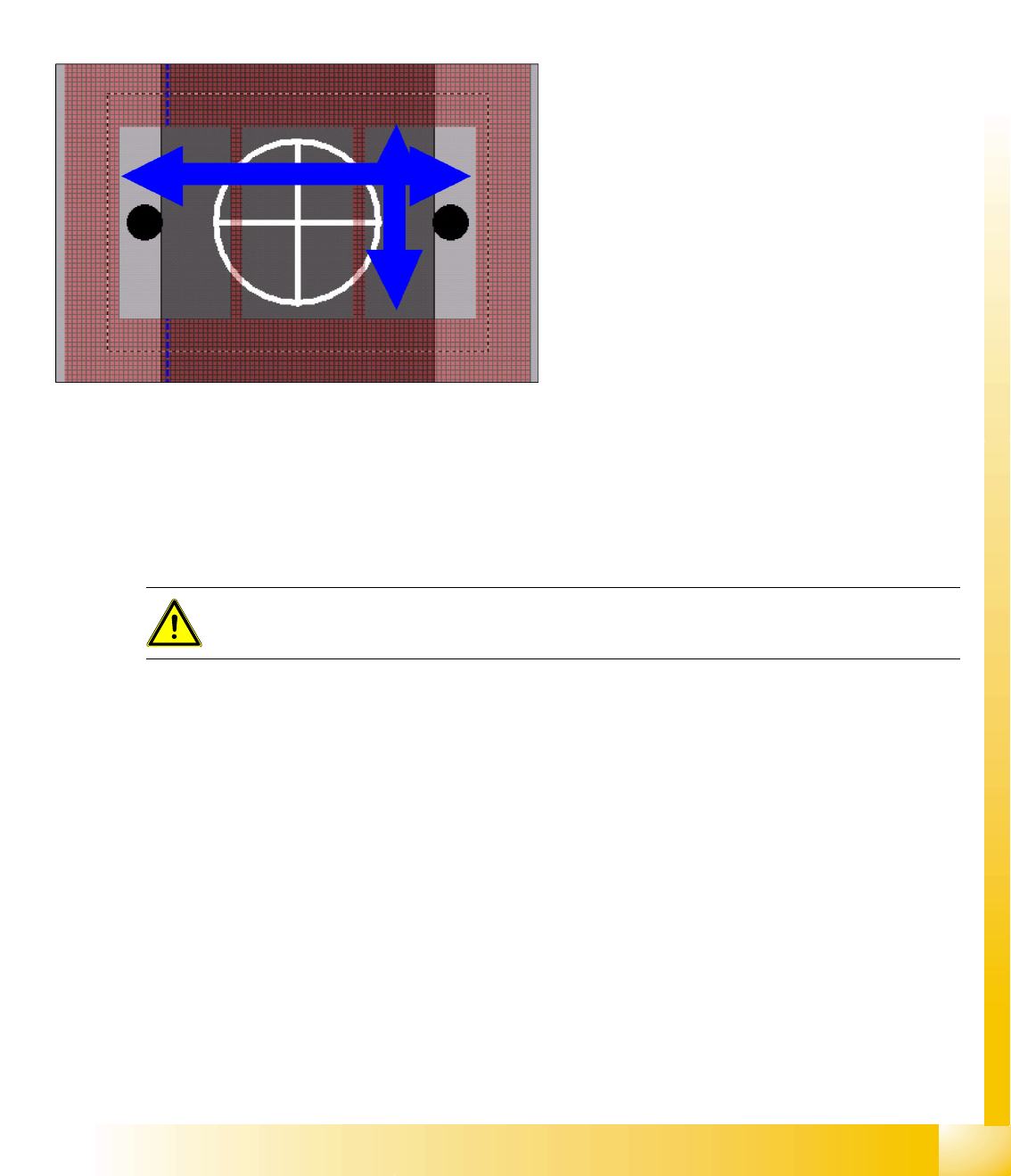
Outer dimensions
The outer length or outer width shown in the diagram above can be used to determine possible
placement problems as these outer nozzle edges or the outer diameter could touch neighboring
components. In the case of extremely small nozzle tips, you can also determine whether these tips can
be inserted into the pickup pockets of the tape or whether they will be seated on the tape surface for
pickup.
Inner dimensions
7.4.2 Component Camera Selected
The camera field of vision shown can be used to determine whether a component with the specified
pickup tolerances can be optically centered. In the case of stationary cameras, you can see whether
multiple measurement is required. (precise Z positioning in the focal height is required for this) You will
not be able to see whether a camera has reached its specific limits.
This shows whether there is a risk that
components which are smaller than the nozzle
surface could be sucked in despite the nozzle
vertical separation which may be present. You can
also determine whether vacuum errors could
occur during component pickup, particularly when
the pickup tolerances are too great.
ATTENTION:
ONLY select
Deactivate Check for minimal Comp.shape structure
in rare exceptions!