SIPLACE Vision Customer_en.pdf - 第70页
Component Shapes Specific Component Shapes Leaded Component Shapes S tudent Guide SIPLACE V ision (Customer) Component Shapes Edition 12/2008 EN 70 Lead description Special features Inspection of th e lead number, pos …
Component Shapes
Leaded Component Shapes Specific Component Shapes
Student Guide SIPLACE Vision (Customer)
Edition 12/2008 EN Component Shapes
69
5.3.7.3 DPACK Component Shape
JEDEC description
JEDEC description
(see TO 243)
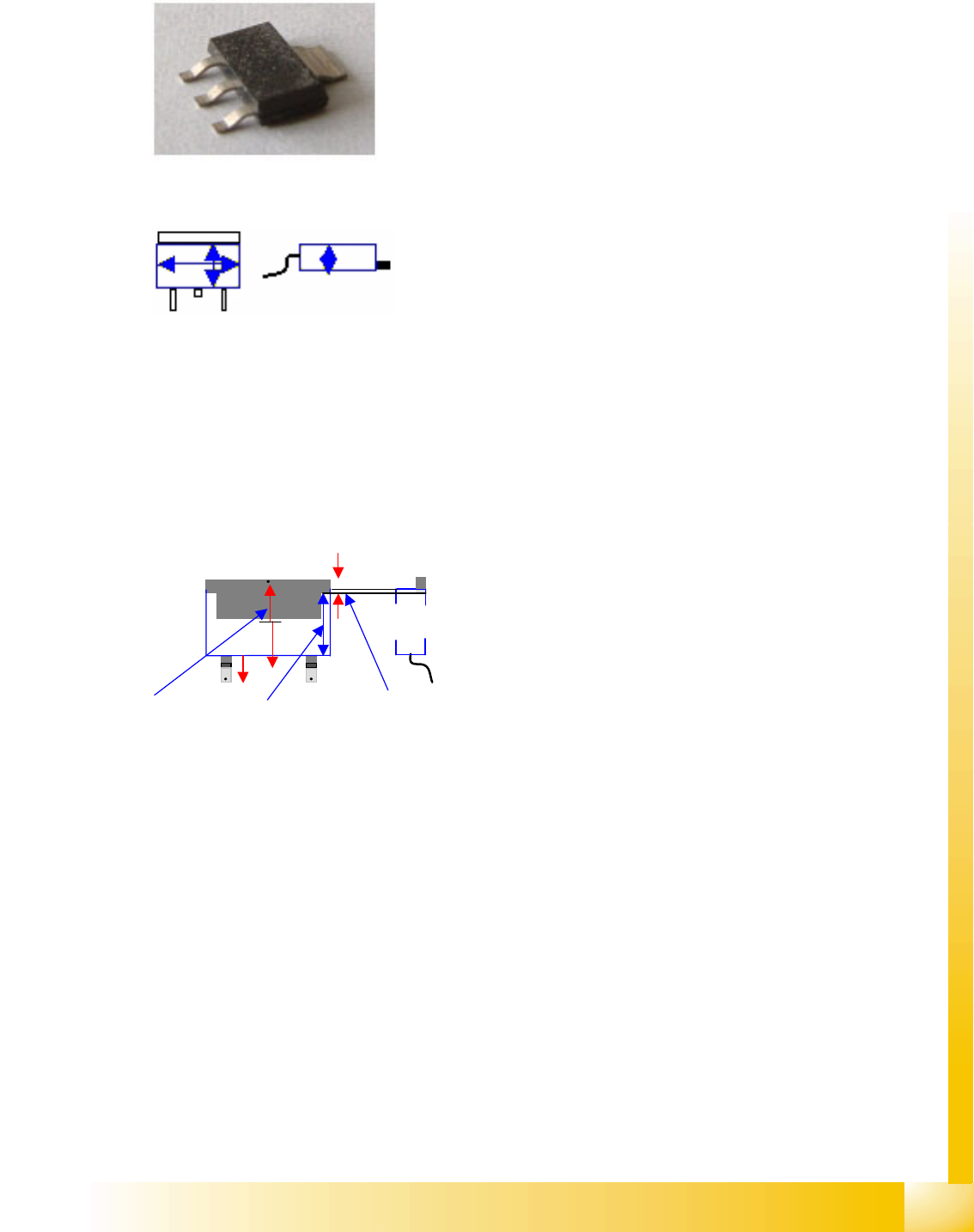
Body description: rectangular.
The Z height of the body determines the measurable height
in the CO sensors.
The X/Y body dimensions determine the field of vision, the
Region of Interest.
This also determines the starting edge of the Gullwing
leads.
This component shape has two (or more) lead groups on
two body sides.
The single lead group (usually heat sink (tab)) must be
described as well. Make sure you do not omit it, otherwise
angle measurement will be problematic. In this group, the
component shape is a Gullwing type (see diagram). This
defines the lead end and the arrangement of evaluation
points.
The contact length and lead length need to be programmed
differently for Gullwings.
The offset values along the Y axis differ due to the different
lead lengths in the opposite groups!
They need to be calculated as follows:
Y-Offset1= body length/2 + lead length1/2
Y-Offset2= body length/2 + lead length 2/2
(Ll1, Ll2)
Component Shapes
Specific Component Shapes Leaded Component Shapes
Student Guide SIPLACE Vision (Customer)
Component Shapes Edition 12/2008 EN
70
Lead description
Special features
Inspection of the lead number, position and pitch is set as a default for these leads and can not be
disabled.
If the CO body does not reach up to the beginning of the leads (due to ICOS), this is only a superficial
programming error, which makes assessment of the DPACK COs slightly more difficult.
There need not always be a centering offset as a result of this.
COPLANARITY measurement is possible provided the option is installed and there are at least three
leads (not in a row) on the body.
Both groups for this component shape must have so-called
Gullwing leads i.e. (normally) leads which are narrower
than the body and have level contact surfaces.
These leads are as wide as the solder resist contact
surface, on the board connection surface. The lead length
is significantly longer than the contact length.
In the single lead group, the lead width must have at least
double the width of the second widest lead.
The leads are outside the body surface. Notches may not
be programmed.
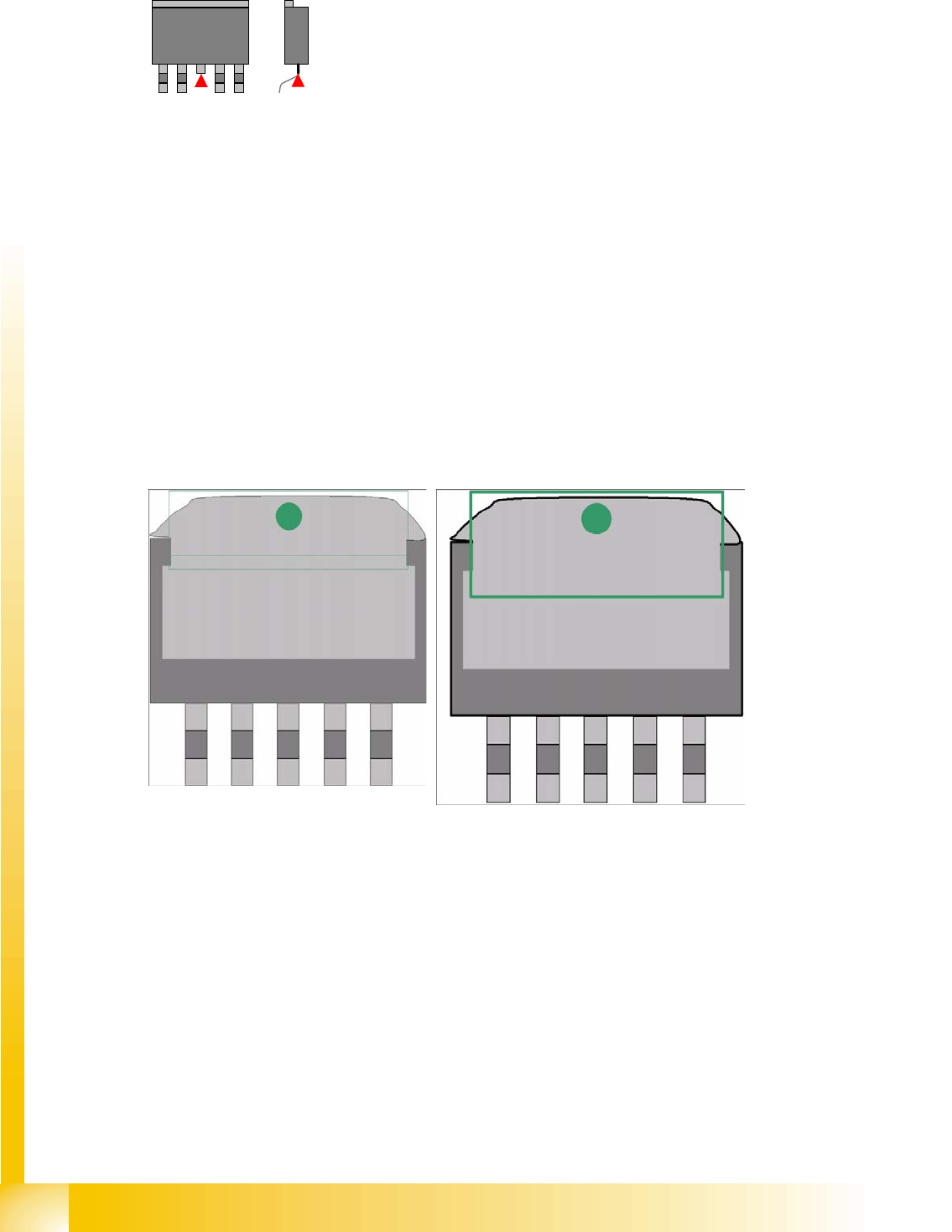
DPACK component shapes have a center lead with no board
contact.
These hanging leads are not important for the placement of
components on the electrical connection surfaces and should
therefore be omitted from the description.
The gullwing leads then need to be divided into two groups
(except for the two contact leads).
If the heat sink (tab) gullwing lead has a slanted edge along its entire length, you will need to extend
the lead length until a vertical lead edge allows you to perform optical recognition.
Gullwing Wraparound
Component Shapes
Leaded Component Shapes Specific Component Shapes
Student Guide SIPLACE Vision (Customer)
Edition 12/2008 EN Component Shapes
71
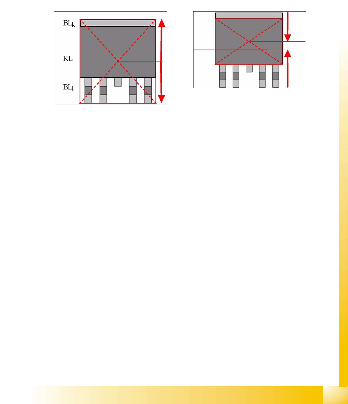
Several description options have been selected for ICOS:
LCU/LRL/ SIPLACE Pro 1.4: the CO center for placement forms the CO center for the overall
dimensions.
SIPLACE Pro 2.0: the CO center for placement forms the body center!
Explanations about Component Center and Body Center
The placement positions for DPACKs, as created by the CAD data, often refer to the center of the CO,
including leads.
Using the body center set in SIPLACE Pro (and the previous programming systems) as the reference
point has the advantage that you are not dependent on differing lead lengths and can always place the
nozzle on the level body center.
This necessitates adjustment of the placement position as follows:
Center displacement = lead length long – lead length short : 2
(If you should make the setting as follows
Lead length short = 1 mm / lead length long = 2 mm and body width = 6 mm
, you will recognize the CO center up to 4.5 mm from above / the body center will be at 4 mm from above.)
The CO center or body center, as determined during centering, needs to be matched with the board X/
Y placement position by the placement machine.