SIPLACE Vision Customer_en.pdf - 第147页
SIPLACE Vision - T eaching Fiducials Trained Inkspots Fiducials for Good/Bad Recognition of panels S tudent Guide SIPLACE Vision (Customer) Edition 12/2008 EN SIPLACE Vision - T eaching Fiducials 147 6.3.3.2 T emplate Fe…
SIPLACE Vision - Teaching Fiducials
Fiducials for Good/Bad Recognition of panels Teach Surface for Inkspots
Student Guide SIPLACE Vision (Customer)
SIPLACE Vision - Teaching Fiducials Edition 12/2008 EN
146
6.3.2 Teach Surface for Inkspots
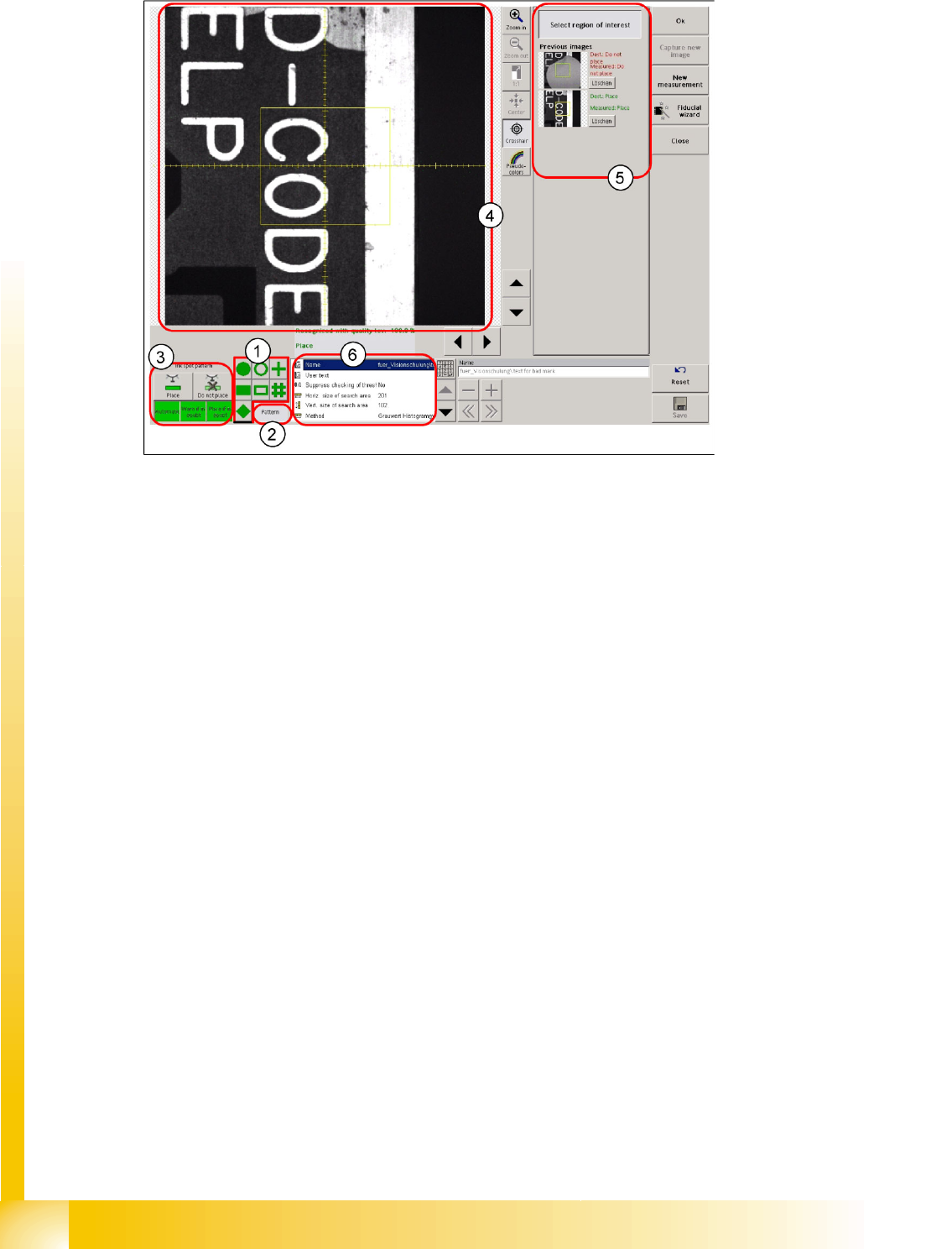
6-13: Teach surface for good/bad teach fiducials
Legend
1. 7 selection buttons for the synthetic inkspot shape
2. Selection button for pattern teaching. The SIPLACE Pro programming system specifies that this
function is for teaching the good/bad state recognition - inkspot - (or position measurement).
3. Function buttons, which can only be selected when teaching inkspot patterns.
4. Evaluation window for inkspots. This is ALWAYS centered around the camera center point!
5. Overview of trained good/bad state fiducials
6. This programming field is normally NOT changed by manual entries during inkspot programming.
However, the method with which good/bad recognition is to be performed is set here (template; gray
value histogram; middle gray value)!
6.3.3 Trained Inkspots
There are several methods which can be used for inkspot classification:
The template method
The histogram method, based on brightness
The middle gray value method, based on brightness
These can be selected while teaching the inkspot pattern.
6.3.3.1 Algorithm Parameters
This parameter setting is not activated for "trained inkspots".
SIPLACE Vision - Teaching Fiducials
Trained Inkspots Fiducials for Good/Bad Recognition of panels
Student Guide SIPLACE Vision (Customer)
Edition 12/2008 EN SIPLACE Vision - Teaching Fiducials
147
6.3.3.2 Template
Features
Relatively high computing time involved
This method evaluates the complete area of the pattern, not just the outline: This therefore does not
need to be defined quite so exactly.
Also requires a defined shape, to which the match is then determined.
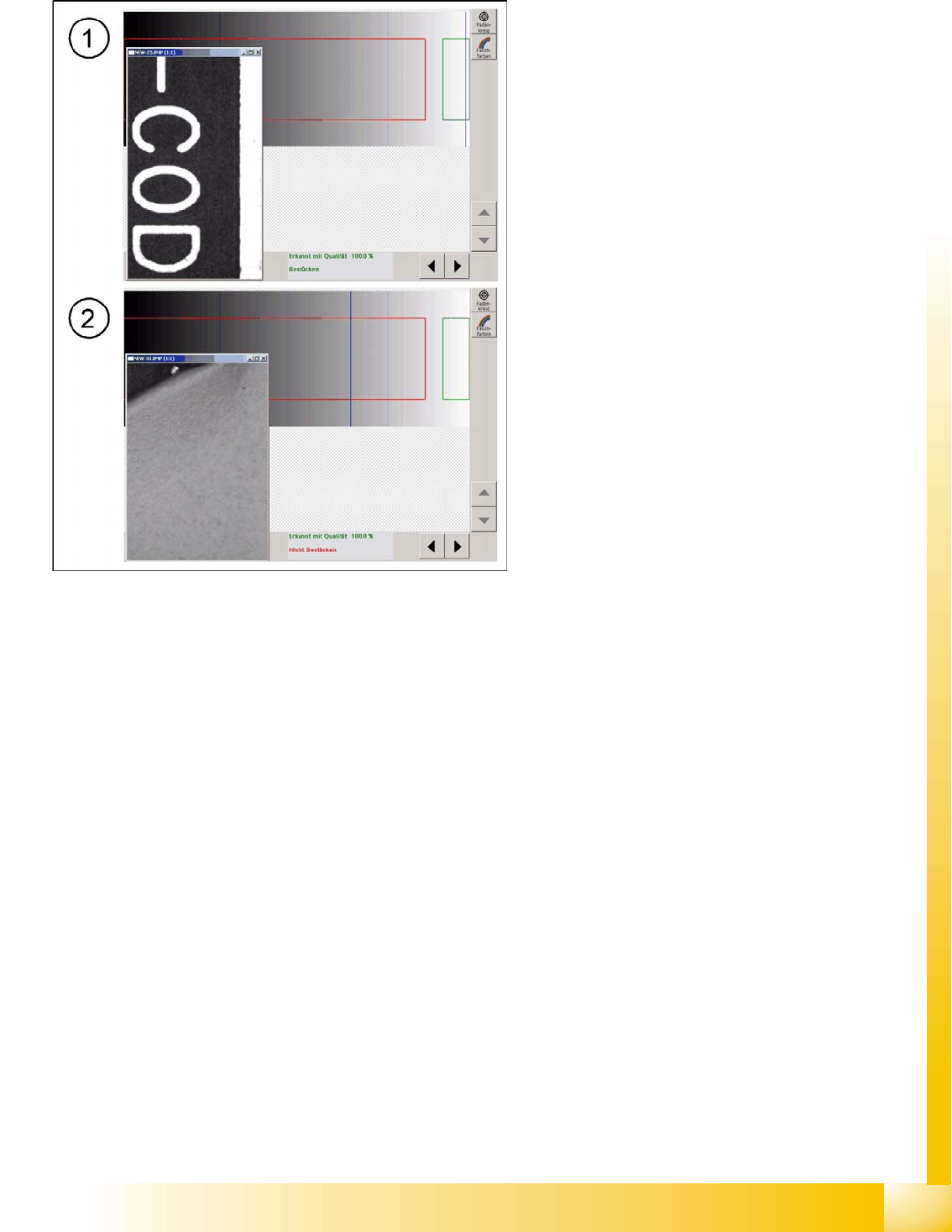
6-14: Good pattern "component" with classification marking "good" fig. 18
bad pattern with classification marking
The template for recognition of the good case is
shown by the pattern in the evaluation field above
the text. The second image needed, for the "bad
case fiducial" is also taught as a template. The
user can change the colors for the bad case label
as required. These can be recognized by the wide
area over which the bad fiducial pattern is
distributed.
The two trained patterns are then always shown
as standardized templates for the placement or
non-placement decision in each fiducial case. This
is why you are only shown the evaluation fields
with their template (pattern) results, here.
The intended application case for this method is
for changing markings on ceramic, with laser
engraving. (if no suitable PCBs are available,
covered fiducials could be used as an exception!)
If there is noise (interference) in the background,
this may prevent a clear assignment to
"placement" or "non-placement", so that the
intermediate area is "in doubt". In this case, you
need to define the following during programming:
That placement is to be performed (the
component should then be relatively low
priced)
That placement is not be performed (the loss
of a panel is better than placement of an
expensive component on a possibly defect
circuit)
SIPLACE Vision - Teaching Fiducials
Fiducials for Good/Bad Recognition of panels Trained Inkspots
Student Guide SIPLACE Vision (Customer)
SIPLACE Vision - Teaching Fiducials Edition 12/2008 EN
148
6.3.3.3 Brightness Histogram
The respective brightness between totally black and white can be seen in the background to the bar
chart.
The brightness histogram for good case recognition is shown by the green bars for brightness
distribution, for the evaluation field above the text.
The second image required, the "bad case fiducial", is shown in the histogram by the red bar on the
respective brightness area of the background.
The operator can not change the colors on the bad case label to any other color.
The brightness distribution of the inkspot to be evaluated is entered as blue brightness bars for various
different image areas and the correlation to the trained brightness distribution of the good/bad case is
checked.
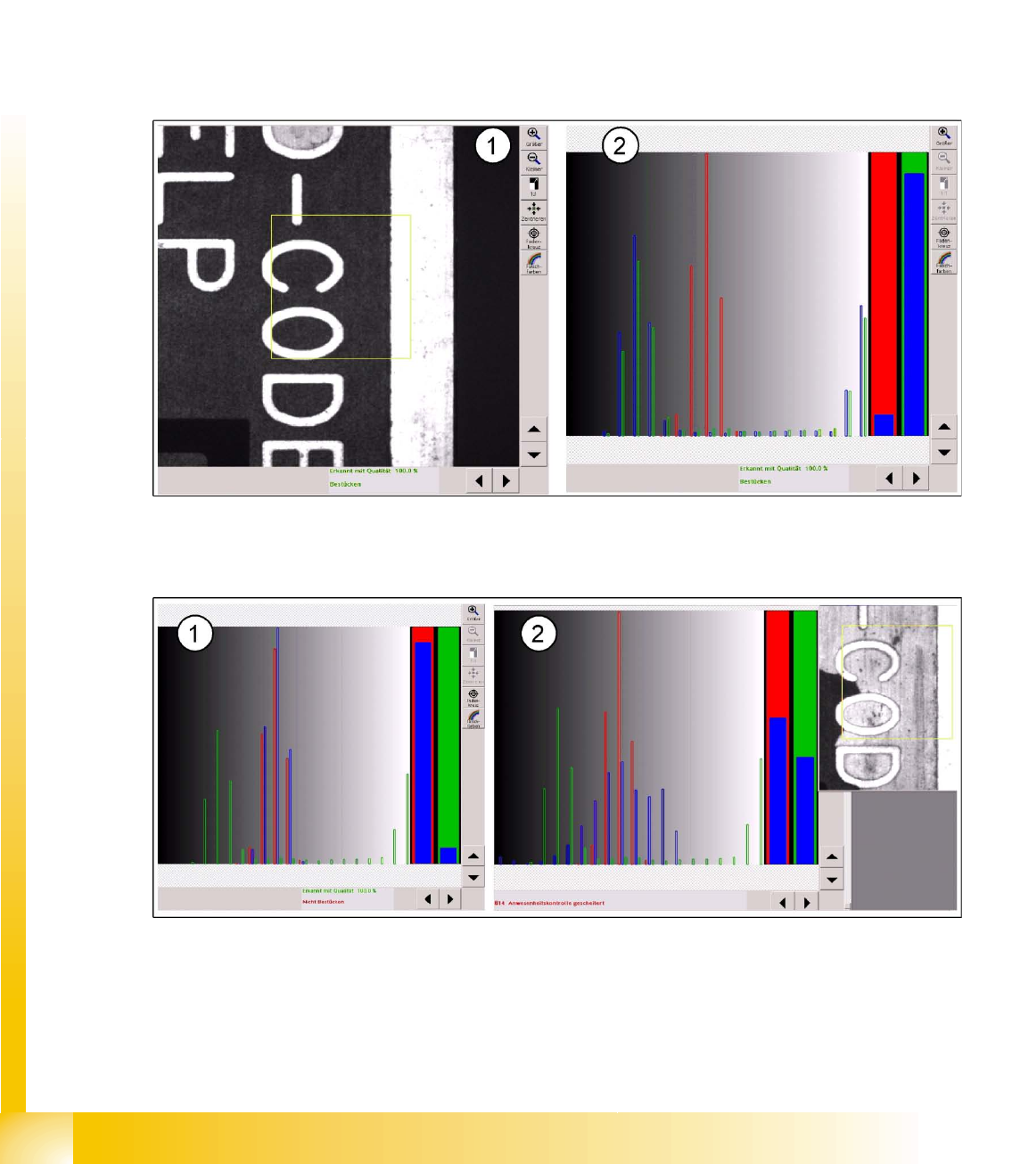
6-15: Evaluation area above the PCB text (1) and brightness distribution for the good case (2)
The percentage correlation of brightness for the evaluation is shown as a quality bar chart (2) before the
respective "good case " (green) or "bad case" (red).
6-16: Brightness distribution for bad case: light label and light background as interference (noise) for inkspot recognition
If the text area is covered with a light colored label, this distribution of brightness will lead to a "non-
placement" classification.
The light background (missing soldering paste) causes an unfavorable distribution of brightness,
meaning that a classification as "good" or "bad" is not possible.
An evaluation based on the middle gray value would result in an assignment to "non-placement".