SIPLACE Vision Customer_en.pdf - 第163页
SIPLACE Pro 3.0 Programming Interface for C omponent Shapes Programming Interface for Body Dimens ions and 'Basics' Programming the Co mponent Shapes in SIPLACE Vision S tudent Guide SIPLACE Vision (Customer) E…
SIPLACE Pro 3.0 Programming Interface for Component Shapes
Converting the Component Shape with LC Import from a UNIX/LINUX Line Computer SIPLACE Pro Reports for LC Import and Conversion
Student Guide SIPLACE Vision (Customer)
SIPLACE Pro 3.0 Programming Interface for Component Shapes Edition 12/2008 EN
162
Correction
CS type correction:) If the component shape needs to be corrected, the edited values will be
overwritten by standard values (without query), if the description rules do not correspond with the
new type.
CS body correction:
If the component body needs to be corrected, the edited values will be overwritten by standard
values (without query).
CS lead type correction:
If the component shape lead type needs to be corrected, the edited values will be overwritten by
standard values (without query).
Additional tools will be provided with SIPLACE Pro 3.1
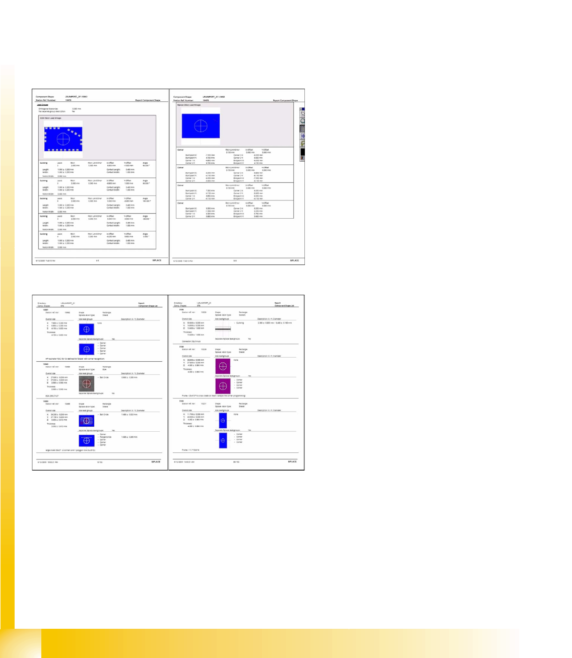
CS report tools:
SIPLACE Pro individual shape report; excerpts
from ICOS and SIPLACE Vision
Changing the lead group offsets directly
influences the placement accuracy or
component placement. SIPLACE Pro 3.1 CS
report via component shape directory or
component shape selection
SIPLACE Pro 3.0 Programming Interface for Component Shapes
Programming Interface for Body Dimensions and 'Basics' Programming the Component Shapes in SIPLACE Vision
Student Guide SIPLACE Vision (Customer)
Edition 12/2008 EN SIPLACE Pro 3.0 Programming Interface for Component Shapes
163
7.3 Programming the Component Shapes in SIPLACE Vision
The SIPLACE Pro component shape editor allows you to program component shapes for optical
centering in SIPLACE Vision (on X machines) and in ICOS systems (on H, HS and S, F machines.
The basic features of the SIPLACE Pro programming interface are shown in the screenshots for the
individual sections.
Use the TAB button to confirm the individual programming values. You can then see whether the
value entered is plausible.
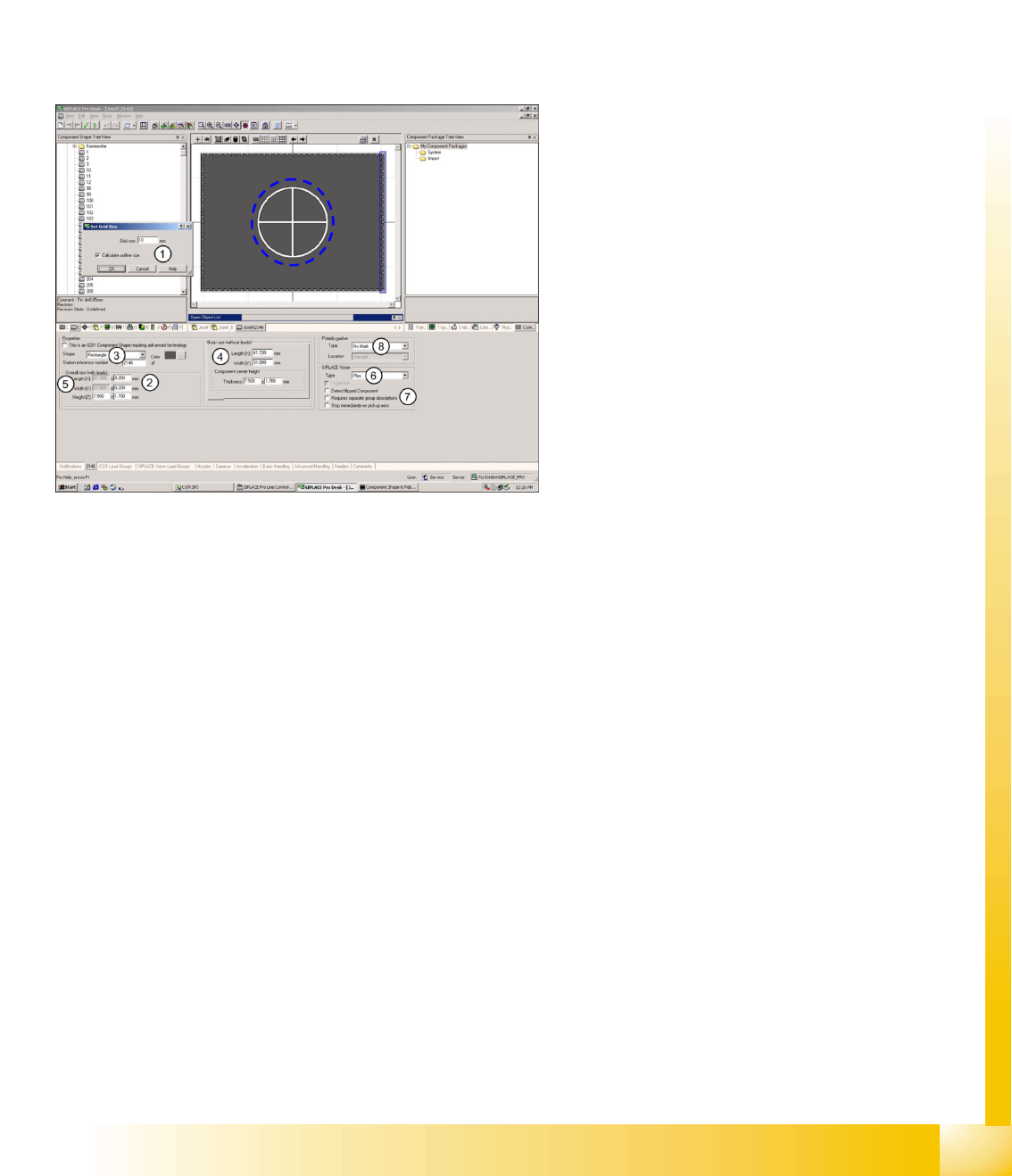
7.3.1 Programming Interface for Body Dimensions and 'Basics'
Legend
1. Option available: window for automatic
calculation of overall dimensions with leads.
2. CS dimensions with leads: X/Y target values
are insensitive when automatically calculated.
3. Body shape: rectangular, horizontal or vertical
(upright) cylinder.
4. Body dimensions without leads: individually
programmable (new) with CO height for CO
sensor
5. Insensitive target values: these will be
automatically calculated if option 2 is set.
6. SIPLACE Vision component type: 17 different
classifications possible. (minimum entry SV!)
7. SIPLACE Vision parameters: inspection
(component-specific); detected flipped
component; Requires separate group
description (for SV and ICOS); stop
immediately on pick up error.
8. Polarity marker in the component diagrams of
the SIPLACE Pro programming interface.
This does not influence optical centering in
SIPLACE Vision or ICOS.
The component diagram in the top middle window
shows the programming parameters for BOTH
Vision systems, if Requires separate group
description was selected and programmed.
SIPLACE Pro 3.0 Programming Interface for Component Shapes
Programming the Component Shapes in SIPLACE Vision Programming Interface for ICOS Parameterization
Student Guide SIPLACE Vision (Customer)
SIPLACE Pro 3.0 Programming Interface for Component Shapes Edition 12/2008 EN
164
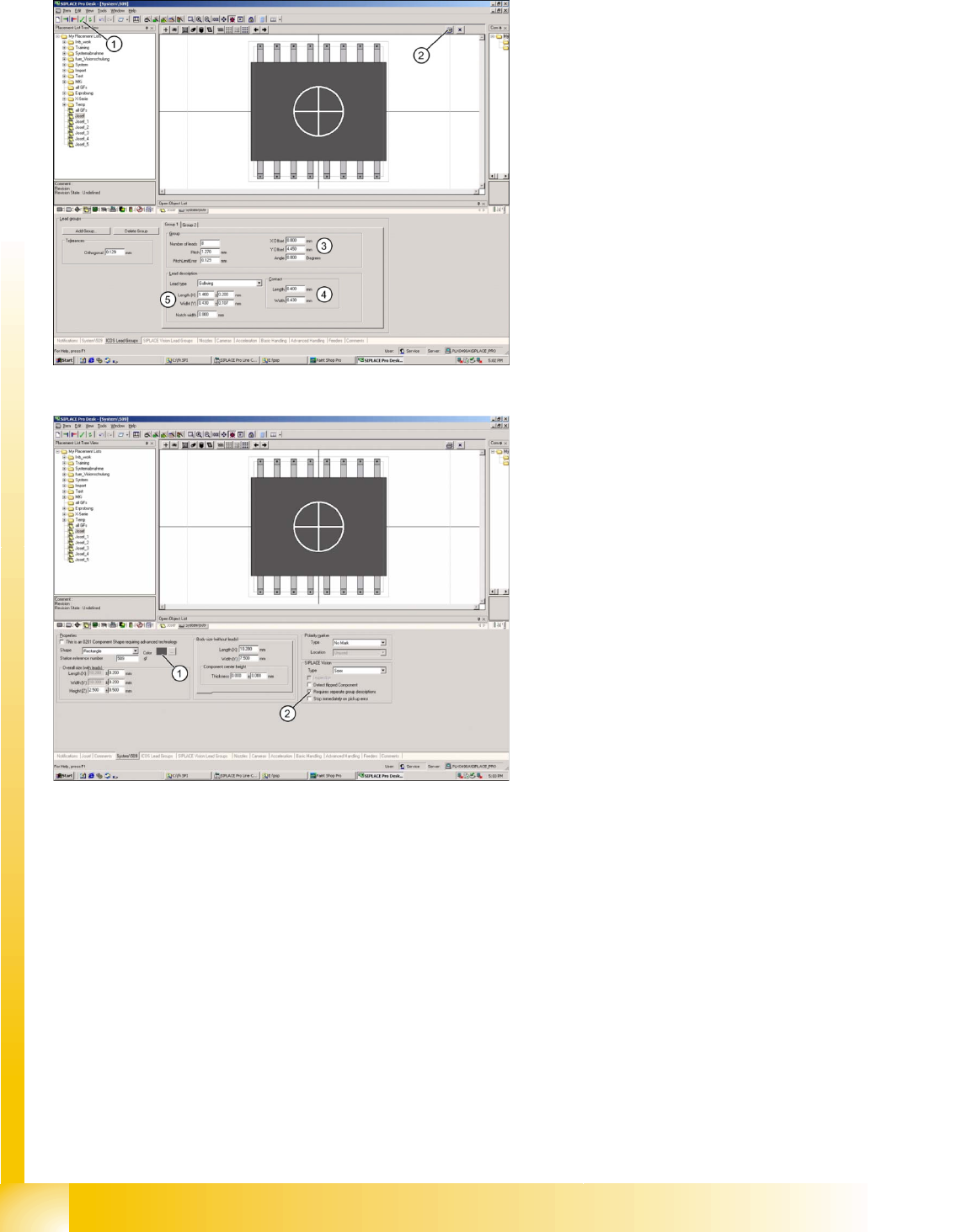
7.3.2 Programming Interface for ICOS Parameterization
Legend
1. Integrity test for component shape in the
editor.
2. Printout of the window contents.
3. Lead group offsets – defines the placement
center of the component.
4. Contact length and width of Gullwing lead.
5. Geometry only for Gullwing/J-Lead/
Wraparound/ Balls (when ICOS and SIPLACE
vision can be edited with the same CS
programming).
Legend
1. The body color can be individually defined for
more clarity e.g. orange for Requires separate
group description.
2. The Vision systems require separate
descriptions for the different lead groups
(Requires separate group description).
In addition detect flipped component (detection of
flipped components) stop immediately on pickup
error (empty track after a previously defined
amount of component pick-up trials) Orientation
(only for component shapes with asymmetric
connectors) Description incomplete and so on can
be selected for these component shapes, when
using SIPLACE Vision at the stations.
The function "Deactivate Check for minimal
Comp.shape structure" allows you to place small
quantities of components which are smaller than
those permitted for the camera specification.
ONLY select this function if absolutely necessary
as the placement accuracy may be less than that
specified on the machine data sheet..