SIPLACE Vision Customer_en.pdf - 第82页
Component Shapes Specific Component Shapes Optical Re cognition and Evaluation of Leaded COs S tudent Guide SIPLACE V ision (Customer) Component Shapes Edition 12/2008 EN 82 Inspection step Lead position in group 1 In th…
Component Shapes
Optical Recognition and Evaluation of Leaded COs Specific Component Shapes
Student Guide SIPLACE Vision (Customer)
Edition 12/2008 EN Component Shapes
81
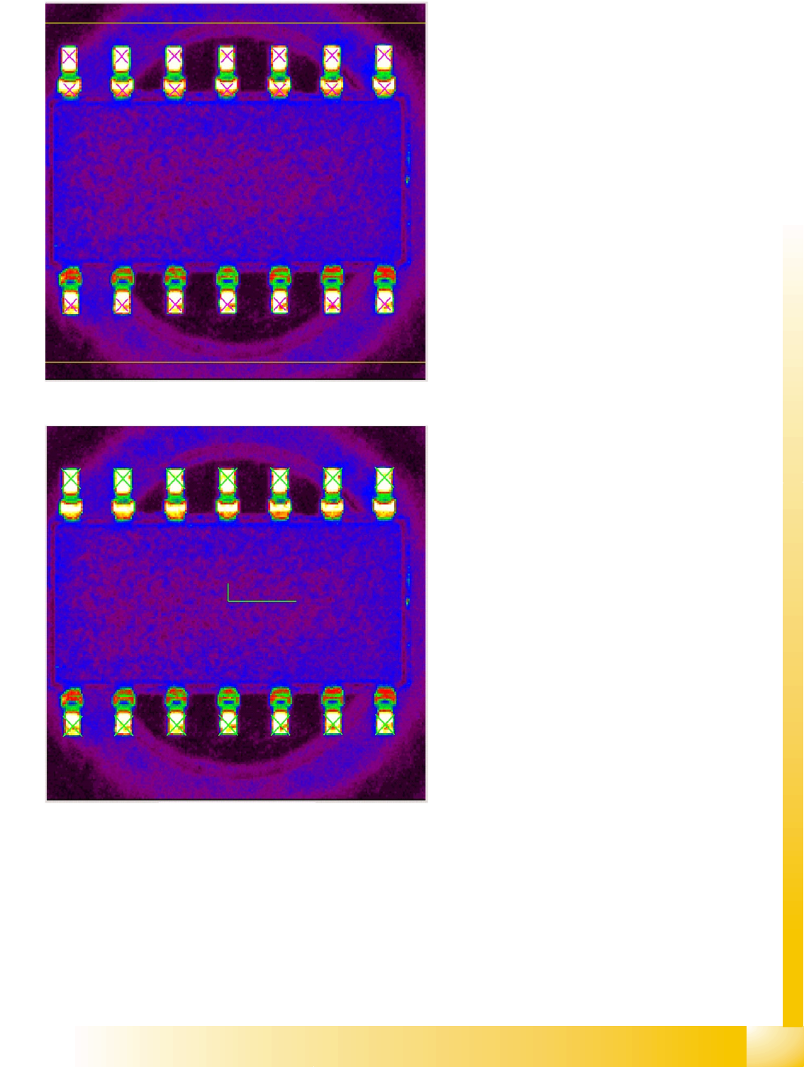
Recognition step Features found
The purple crosses mark the surfaces of the lead
candidates.
In the next step, the distance between the lead
candidates is checked. Candidates which do not
fulfill this criterion will be singled out.
Recognition step Recognized model
The green crosses mark the contact surfaces of
the lead models.
The green tick shows the CO center for
placement, calculated from the lead positions. The
CO position is therefore determined and CS-
specific CO inspection can begin.
Component Shapes
Specific Component Shapes Optical Recognition and Evaluation of Leaded COs
Student Guide SIPLACE Vision (Customer)
Component Shapes Edition 12/2008 EN
82
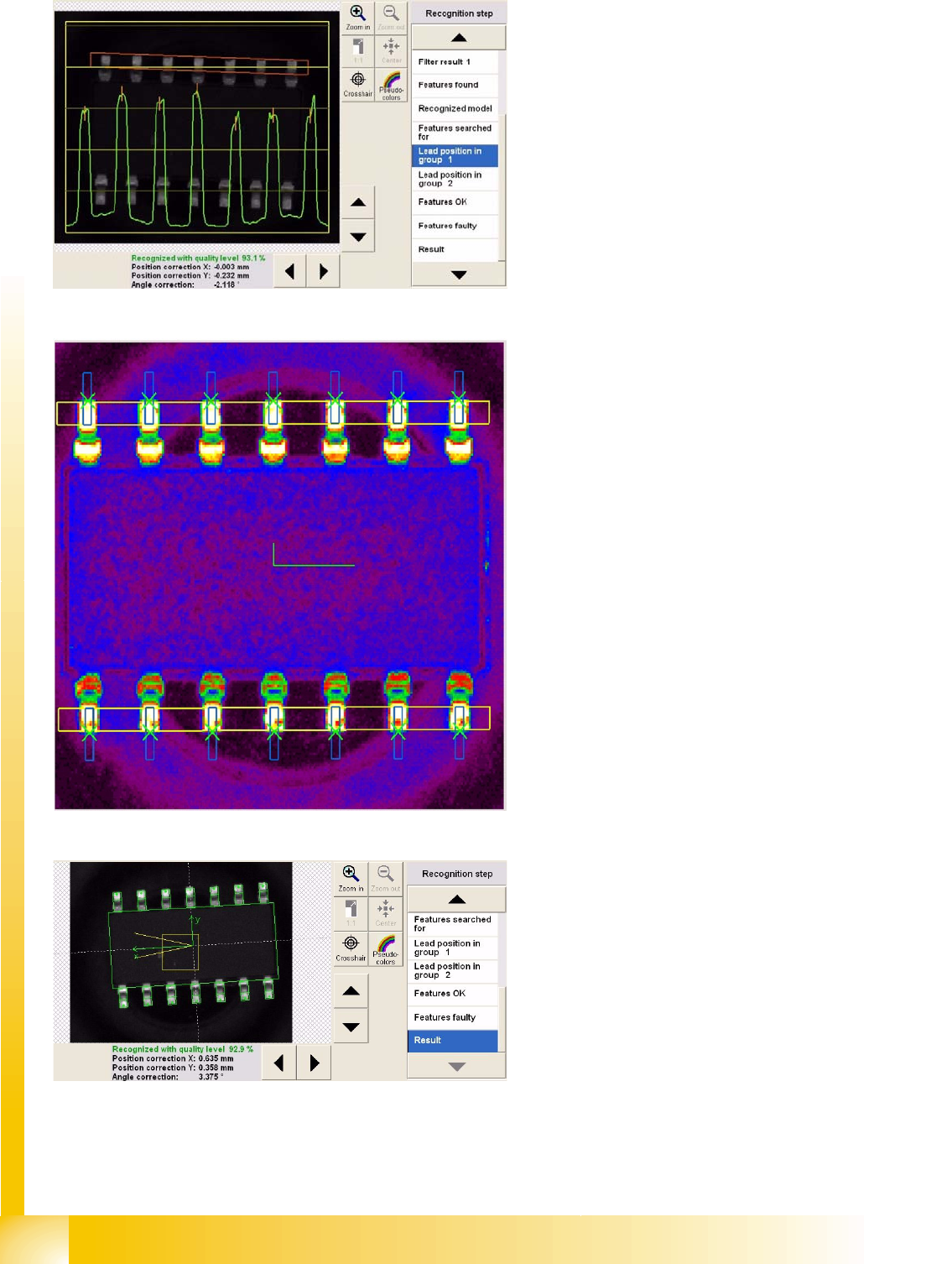
Inspection step Lead position in group 1
In this step, the lead gray value profile (green) is
determined for the region inside the red group
window.
In this step, the lead gray value profile (green) is
determined for the region inside the red group
window.
Determination of the lead end edge is also
performed, although this will not be shown in the
diagram.
Recognition step Features OK
The lead outer edges are searched for in the blue
window.
The measured lead pitch is marked by the green
crosses at the lead ends.
This is marked on the lead outer edge line in the
analysis presentation.
The green tick shows the determined CO center.
Features which - for whatever reason - were not
recognized, are marked as such in the Features
faulty menu, (in red).
Result of centering with inspection
Component Shapes
Optical Recognition and Evaluation of Leaded COs Specific Component Shapes
Student Guide SIPLACE Vision (Customer)
Edition 12/2008 EN Component Shapes
83
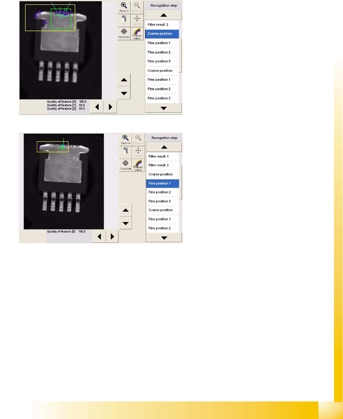
5.3.8.2 Recognition of Very Wide Leads
Heat sink (tab) and ground connection leads are often produced as overwide leads. They need to be
included in the programming, otherwise the angle calculation step will deliver incorrect results, if there
are too few leads on the opposite side or if the lead rows are too short.
Recognition step Coarse position 1
This step measures the outer edges (1) with the
help of brightness evaluation, performed vertically
to the lead in the region around the light blue Vs.
This step also determines the lead center (2) at the
outer edge in the left measurement window (the
same procedure is used for coarse/fine position 2
in the right-hand window).
Finally, the left side edge is determined. The
procedure here is to set the image point pairs so
low that the normal slant of the side edge is not
included in the measurement.
Recognition step Fine position 1
Several point pairs are now used to determine a
fine position and fine angle, within the position
defined during the step Coarse position1.
As described for SO components, the same
process is applied to the leads in group 2.
Lead inspection is then performed for the
recognized lead positions.