SIPLACE Vision Customer_en.pdf - 第87页
Component Shapes Components With Round Leads Specific Component Shapes S tudent Guide SIPLACE Vision (Customer) Edition 12/2008 EN Component Shapes 87 Description CO Height JEDEC description Lead description This compon …
Component Shapes
Specific Component Shapes Components With Round Leads
Student Guide SIPLACE Vision (Customer)
Component Shapes Edition 12/2008 EN
86
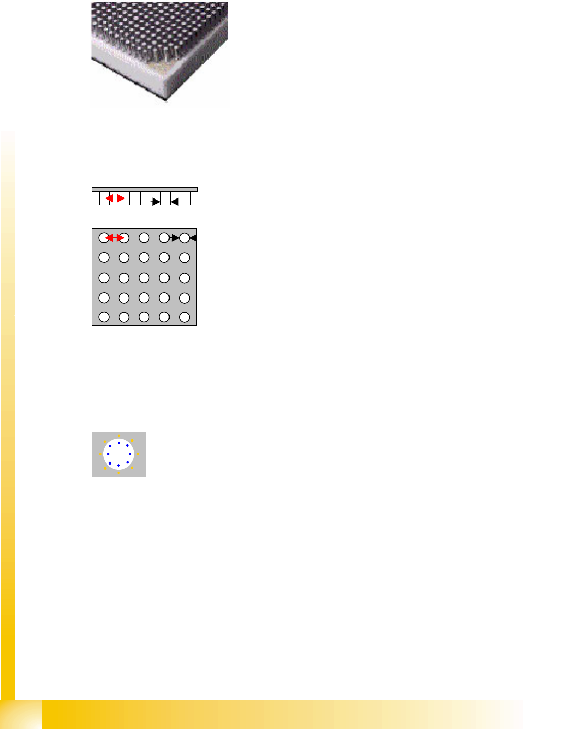
5.3.9.2 CCGA Component Shape (Ceramic Column Grid Array)
JEDEC description
Group description
Lead description
This component shape has so-called Column leads. The column diameter and column tolerance must
be identical for all groups.
Special features
Joint datasets with ICOS data NOT possible
Component Shapes with Through Hole Pins
Components originating from board production using through-hole technology, are becoming
increasingly popular in SMD production processes. This method is often known as PIN-in-Paste
technology.
No JEDEC description, as defined by IBM.
Body description: rectangular.
The Z height of the body determines the CO height for the
Z positioning profile.
The X/Y body dimensions determine the field of vision, the
Region of Interest.
The body size should be adjusted to reflect the real body
size and not just cover the size indicated by the column
leads.
The leads are distributed throughout the CO surface, as
column-shaped contacts which are arranged in a matrix .
This shape can contain one or more groups. Leads may be
missing in the rows or columns.
The (pitch) and pitch tolerance for the column arrangement
must be identical in all groups.
The pitch is greater than the column diameter, even with
individual round leads.
The contrast between the body and the Ball lead can be set
as required. The lead is similar to BGA, although the
Column type requires different illumination and filtering of
the optical presentation.
Missing columns will not be recognized, since the
illumination selected recognizes the columns and the round
surfaces below as the same shapes.
You can also select an option for inspection of column
presence and arrangement.
Component Shapes
Components With Round Leads Specific Component Shapes
Student Guide SIPLACE Vision (Customer)
Edition 12/2008 EN Component Shapes
87
Description
CO Height
JEDEC description
Lead description
This component shape has so-called Column leads. The column diameter and column tolerance must
be identical for all groups.
Body description: usually rectangular.
The X/Y body dimensions determine the field of vision, the
Region of Interest.
The body size should be adjusted to reflect the real body
size and not just cover the size indicated by the column
leads.
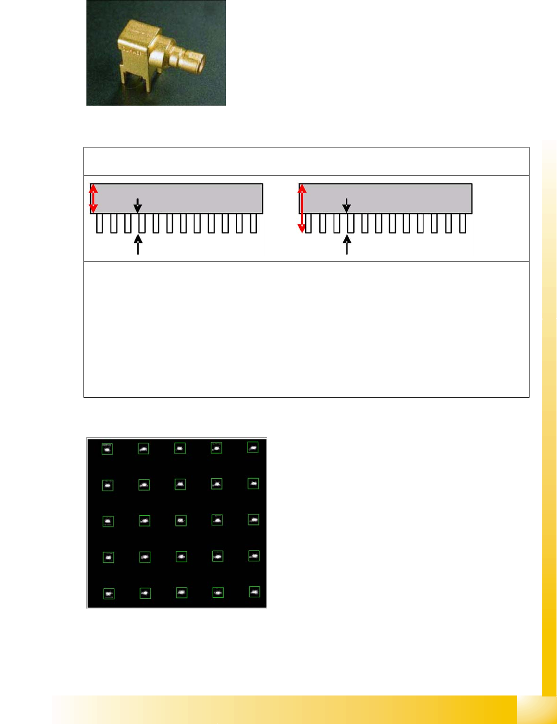
An individual inspection step, based on exact knowledge of the detailed dimensions and the required placement
process, determines the CO height.
The programming of the CO height, from the
nozzle contact level to the required contact height
on the board, achieves such a low (deep) target
position for the Z-axis travel profile, that the pins
are pressed through the board .
Very high pins may therefore be outside the focal
area of the IC camera, meaning that very small
structures will be recognized with measurements
variance. Furthermore, collisions may occur with
previously placed, unusually high COs.
The programming of the CO height, from the nozzle
contact level to the tip of the through-hole contacts,
achieves a Z-axis travel profile in which the Z-axis inserts
the pins through the relatively wide holes, at low speed,
while learning the deeper placement levels. Placement
with snap-in pins is hardly possible, since higher forces
cause the Z-axis to recognize the end of the placement
procedure before it should.
The pin tips to be recognized are located in the IC
camera region of focus or, in other words, the lower edge
of the pin is well above the theoretically highest (25 mm)
previously placed CO.
The leads are distributed throughout the CO
surface, as column-shaped contacts which are
arranged in a matrix . Refer also to the relevant
explanations for CCGA component shapes.
Component Shapes
Specific Component Shapes Components With Round Leads
Student Guide SIPLACE Vision (Customer)
Component Shapes Edition 12/2008 EN
88
Note: A small pitch tolerance and diameter tolerance must guarantee that the PCB drilling is accurately
touched. Support the PCB area for this TH placement well so that the PCB is not bent, leading to
additional insertion errors with the pins.
Types
Key points for placement – Z-axis dynamics downwards – :
If pins or contacts or inserted through the board holes, make sure that the placement force is
programmed sufficiently high.
You will also need to set a low travel speed. Select a travel profile with Slow braking (profile 6 or 8).
This currently means that the axis travels the last ~1 mm (before reaching the placement height) at
its slowest speed.
If the board holes are large enough to make increased force unnecessary (example 1), you can use
the timesaving standard travel profile.
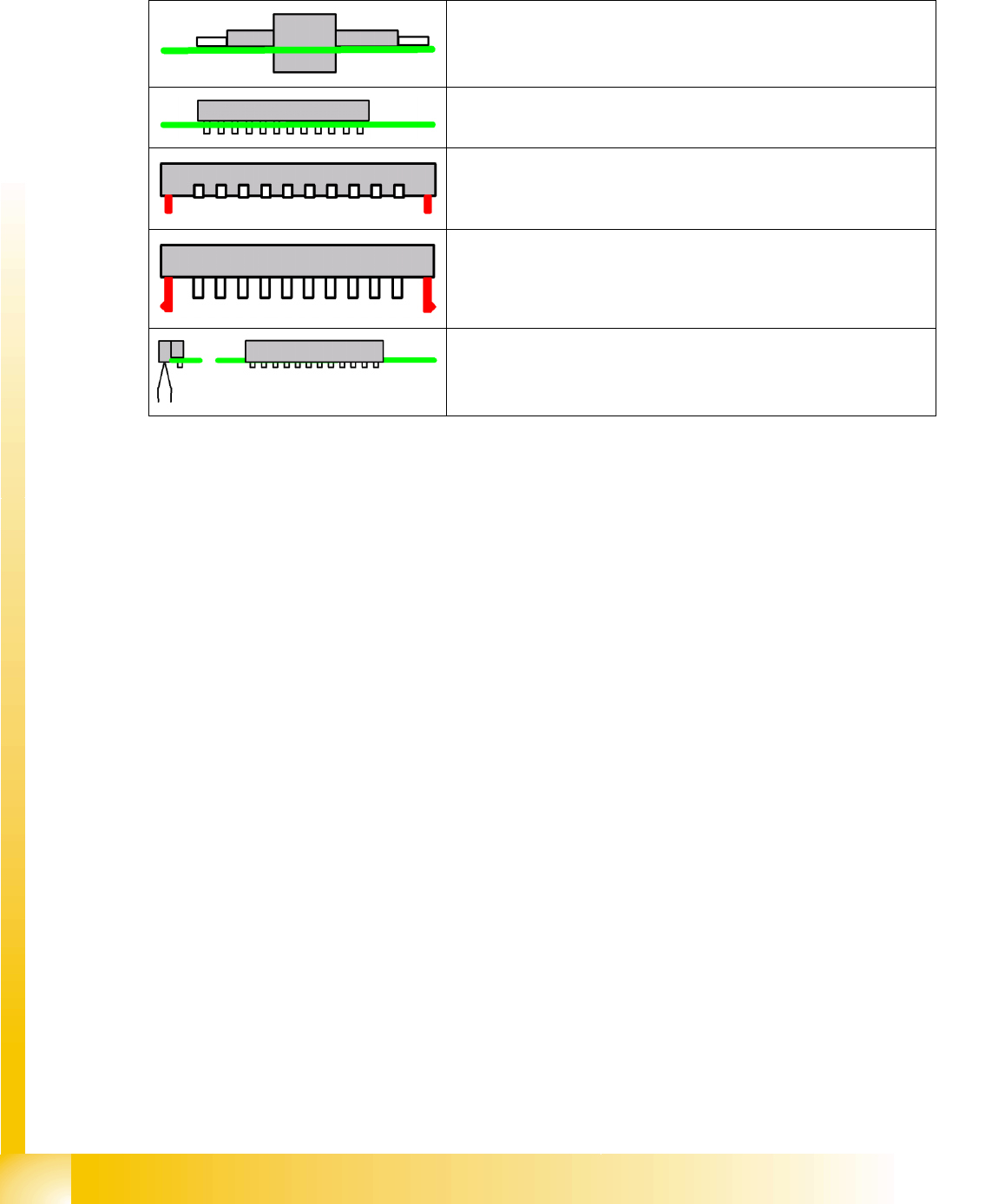
Components on which the parts protrude through the PCB cutouts
Components on which the electrical contacts protrude through the
board.
Components with additional centering pins.
Components with locking pins; these require a significantly higher
placement force (see Options).
Connectors aligned away from the board or related combinations.
Appropriate PCB supports are required under the nozzle contact point.