SIPLACE Vision Customer_en.pdf - 第131页
SIPLACE Vision - T eaching Fiducials Placement Position Recognition What are Fiducials? S tudent Guide SIPLACE Vision (Customer) Edition 12/2008 EN SIPLACE Vision - T eaching Fiducials 131 6.1.2 Placement Position Recogn…
SIPLACE Vision - Teaching Fiducials
What are Fiducials? PCB Position Recognition Fiducials in the PCB Layout
Student Guide SIPLACE Vision (Customer)
SIPLACE Vision - Teaching Fiducials Edition 12/2008 EN
130
Fiducial arrangement layout
When arranging fiducials for PCBs with multiple consolidated panels, this arrangement of fiducials can
either be recorded once for the entire PCB or each of the individual switching circuits can be assigned
its respective fiducials and recorded.
You can not program and use the PCB position recognition both for the entire board AND for a single
panel at the same time. If this is programmed, the PCB position recognition will give the panel priority
and the fiducials for position recognition of the entire board will not be approached and centered.
The following description explains the special case of the "long board" option.
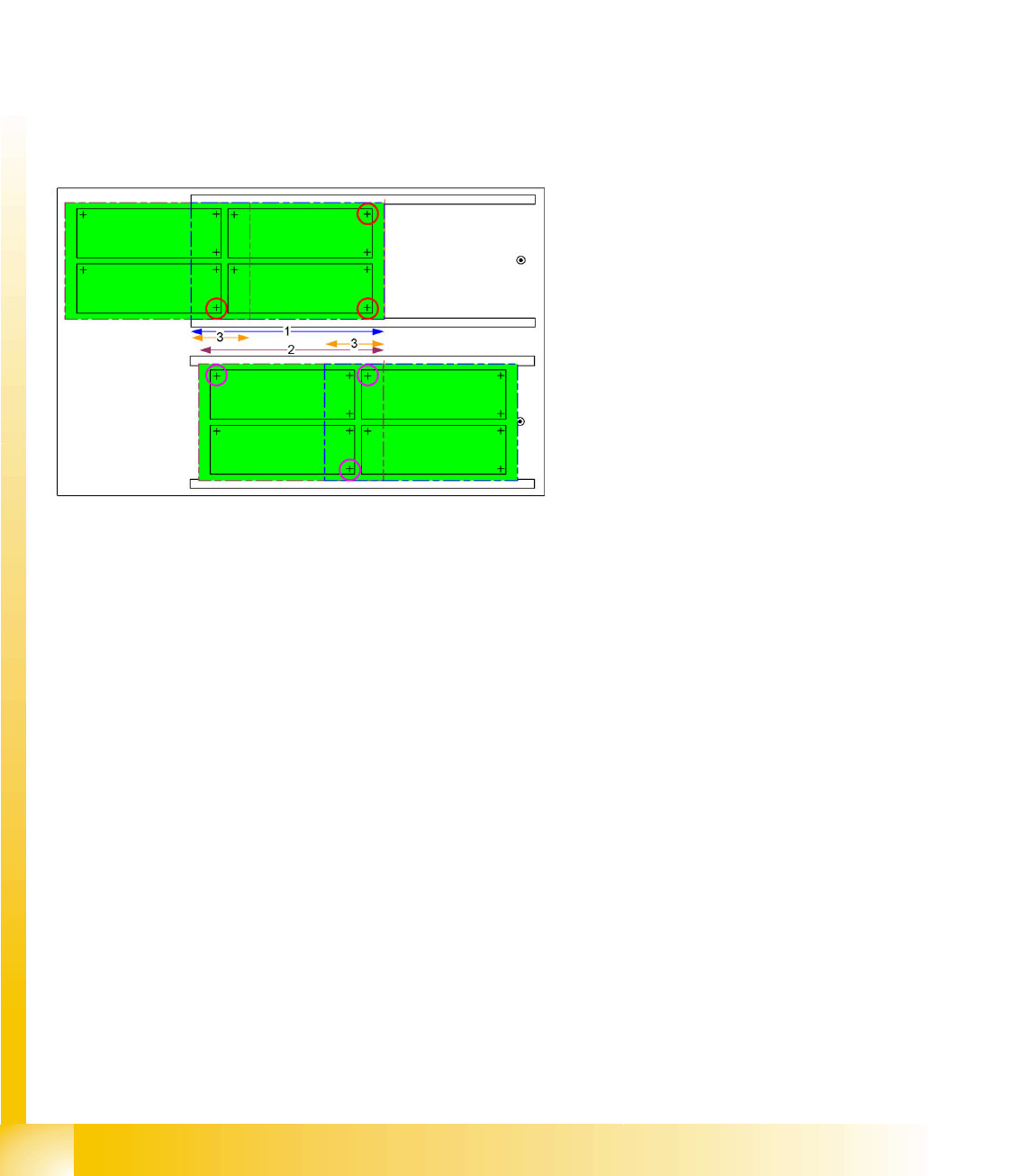
Layout for fiducial arrangement if the "long board" option is used
In the long board option, the PCB is stopped twice in the placement area of the machine: once at the
laser light barrier – PCB placement area of the 1st stop and then at the mechanical stopper of the long
board option - PCB placement area of the 2nd stop. 3 fiducials for PCB position recognition can be
distributed throughout the length of the relevant placement stop area.
Fiducials in the overlap area can be used for position recognition of both the 1st and the 2nd area. This
means that 4 to 6 fiducials in total can be programmed for position recognition of a "long board".
As can be seen in the diagram labeled "Non-recommendable arrangement of PCB position recognition
fiducials" (see above), it is not advisable to concentrate the PCB position recognition fiducials for both
placement areas just in the overlap area.
Fiducials in the panels if the "long board" option is used
If all fiducials and placement positions are in the placement area of the respective stop, you can also use
the position recognition fiducials for the panels (see the 3 crosshairs in each panel).
If one placement position is located in the placement area of the other stop, this type of PCB position
recognition will not function in the machine with the long board option.
After performing PCB position recognition, the fiducials for other optical PCB recognition runs will be
approached. From the introduction of SIPLACE Vision, position recognition is ALWAYS performed
BEFORE inkspot recognition.
6-3: Possible distribution of PCB position recognition fiducials for long board
option
The PCB stopped at the laser light barrier can be
placed in the area marked as '1'.
2 fiducials from the front row of 4 fiducials and one
fiducial in the overlap area (2nd row of four) form
the 3 fiducials for the placement area of the 1st
stop.
2 fiducials in overlap area ’3’ and one in the row of
2 fiducials at the end of the PCB form the fiducials
for the placement area of the 2nd stop (arrow ’2’)
at the mechanical stopper for the long board
option.
SIPLACE Vision - Teaching Fiducials
Placement Position Recognition What are Fiducials?
Student Guide SIPLACE Vision (Customer)
Edition 12/2008 EN SIPLACE Vision - Teaching Fiducials
131
6.1.2 Placement Position Recognition
A fiducial on a PCB can also be used for exact measurement of a placement position. The position
coordinates relate to the Overall PCB zero point or the Panel zero point and not to the placement
position to be measured. The fiducials can either be positioned diagonally on the corners of the
placement layout at the placement position or in the center. The measurement results and centering
steps for PCB position recognition or placement position determination do not differ from one another!
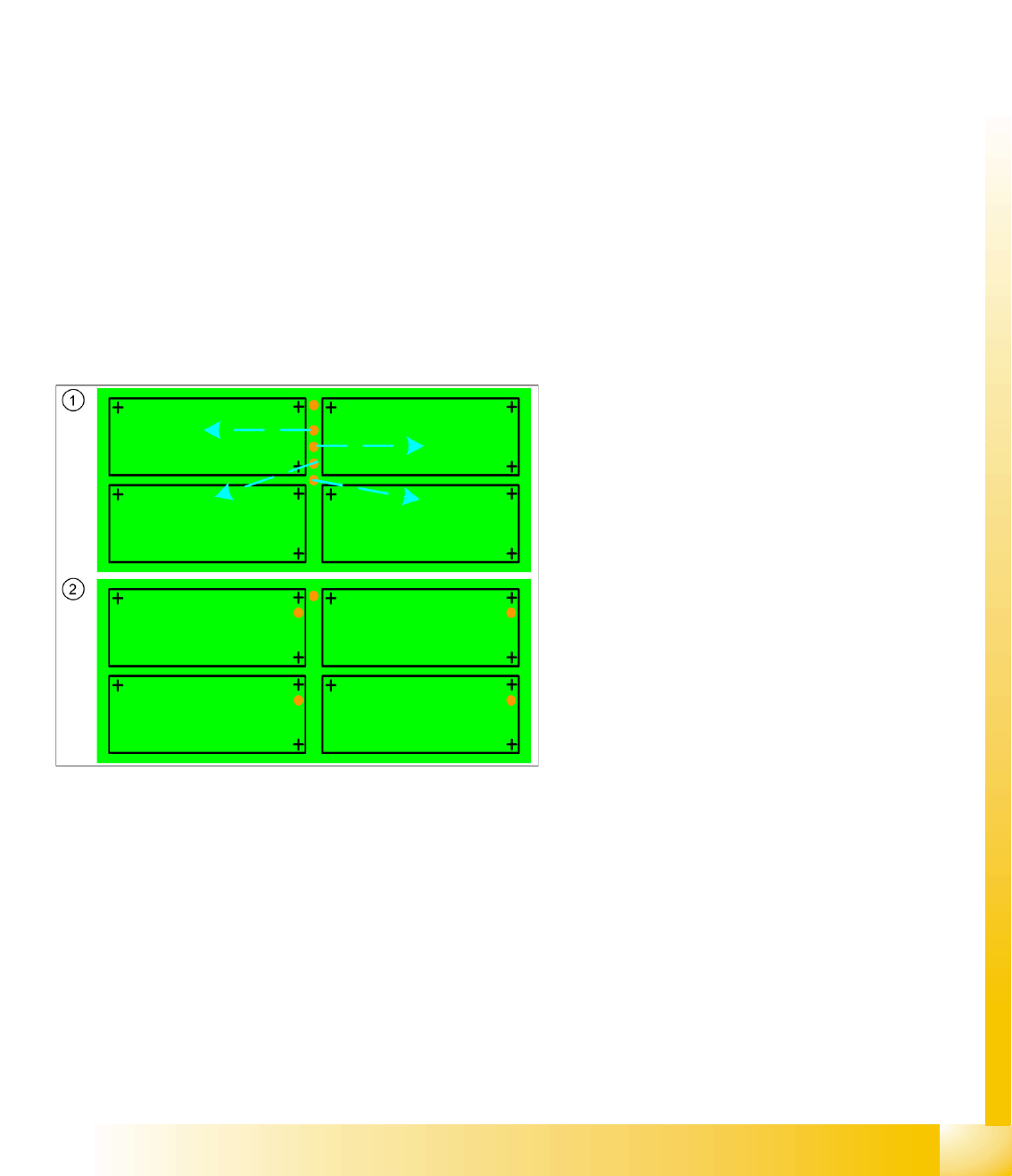
6.1.3 Good/Bad Board Recognition of So-Called Inkspot Recognition
Boards with multiple panels often need to have panels with a defect or ones for prior production omitted,
so that expensive components are not placed where it is not necessary.
In contrast to the two previous applications, explained above, this procedure does not involve
determining position coordinates during the fiducial measurement but, instead, just the relevant optical
impression, brightness or contrast.
To save time, a so-called "global inkspot" has been created.
When recognized as OK, this global inkspot defines that all panels are OK and suitable for
placement.
If recognized as bad, this global inkspot defines that at least one panel is NOT OK and is therefore
to be omitted after the relevant fiducials have been scanned.
The fiducial for good/bad panel recognition is often also on the overall PCB. This saves placement space
on the individual panel, although it does make work more difficult for the programmer and line operator.
Legend
1. Inkspot fiducials for panels on the entire PCB
frame or edge
This arrangement of inkspots requires
individual programming of each panel!
It is also essential that the operator knows
which inkspot is assigned to each panel.
2. Inkspot fiducials in the panels
In the standard arrangement of inkspot
fiducials in the panel , this is "automatically"
clear due to the duplicate arrangement in the
panel.

SIPLACE Vision - Teaching Fiducials
Fiducial shapes Synthetic Fiducials for Position Recognition Applications
Student Guide SIPLACE Vision (Customer)
SIPLACE Vision - Teaching Fiducials Edition 12/2008 EN
132
6.2 Fiducial shapes
One fiducial shape can be used for all the applications described above. However, since one application
uses position measuring algorithms and the other application (inkspot) does not, this shape will need to
be trained twice.
This means:
A fiducial shape is trained for the fiducial library in SIPLACE Pro and can then be called up for PCB
programming and supplemented with coordinates and the respective position measurement
application.
A fiducial shape is trained for the fiducial library in SIPLACE Pro and can then be assigned
coordinates, so that the gantry can position the camera for good/bad recognition.
See also the programming guides in SIPLACE Pro x.x
6.2.1 Synthetic Fiducials for Position Recognition Applications
Fiducials which have shapes which are symmetrically arranged around a center point can be easily
described and recognized.
Synthetic fiducials are more exact than sample fiducials, as the inaccuracies of the so-called "gold
sample", to be learnt, do not apply.
The following parameters are sufficient for the description of these fiducials:
The shape (cross, circle, ring, rectangle (special shape: square), rectangular ring, 45° square
(diamond), doublecross)
The size or other dimensions such as bar width
The contrast to the background (fiducial bright or dark)
Using these specifications, the outer edges can be determined and taken for rough (coarse) and fine
structure recognition.
Since SR/MC 603.xx, synthetic fiducials can also be trained with a fiducial wizard.