SIPLACE Vision Customer_en.pdf - 第55页
Component Shapes MELF Component Shape Specific Component Shapes S tudent Guide SIPLACE Vision (Customer) Edition 12/2008 EN Component Shapes 55 5.3.4 MELF Component Sh ape JEDEC description JEDEC description This compo…
Component Shapes
Specific Component Shapes CHIP Component Shape
Student Guide SIPLACE Vision (Customer)
Component Shapes Edition 12/2008 EN
54
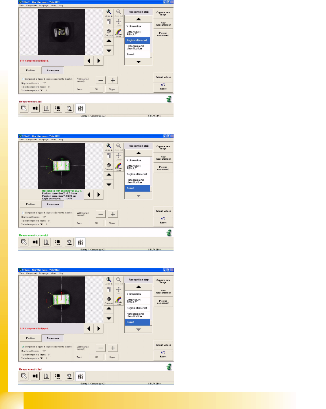
If this default setting (with a threshold of 127) is not adequate for reliable recognition, the required
threshold can be trained in the algorithm parameters of the SIPLACE Vision menu (CS measurement
modes in ICOS) Face Down.
Example C:
The diagram shows a flipped CHIP component.
The threshold has been raised to 154 and the
errors were recognized correctly.
Example D:
The diagram shows the teaching procedure for a
correctly recognized CHIP component. The
threshold has been increased to 126 and the
component was recognized correctly.
Example E:
Check this box to invert the evaluation. In this
case, all brightness values above the threshold will
now be interpreted as CO top side. The previous
teaching values will be reset.
Component Shapes
MELF Component Shape Specific Component Shapes
Student Guide SIPLACE Vision (Customer)
Edition 12/2008 EN Component Shapes
55
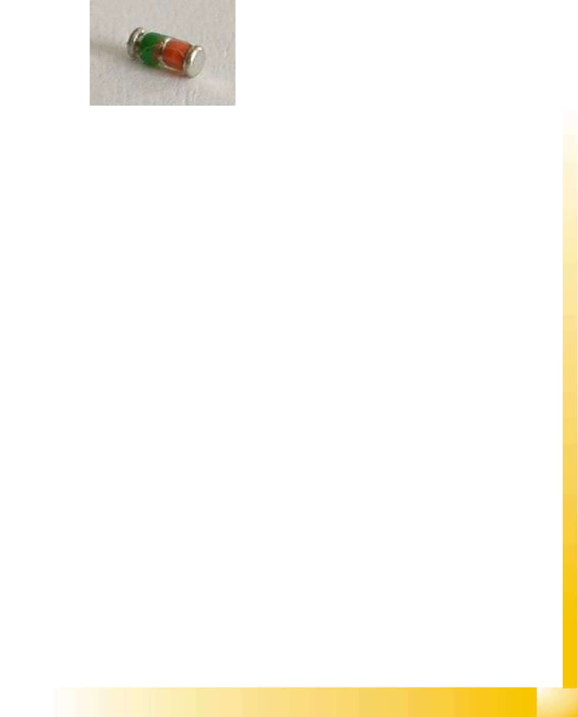
5.3.4 MELF Component Shape
JEDEC description
JEDEC description
This component consists of two lead groups, each with one lead.
The leads in the two groups must be identical!
This defines the lead direction: towards the CO center.
The leads are inside the body surface.
In the case of this component, the leads are understood to begin where the body begins, meaning
that a group offset does not need to be programmed.
After optical centering, the distance between the leads and the center (body center) is measured and
used for the placement coordinates.
Lead description
This component shape has so-called Wraparound leads, which are wrapped around the component
body, hence the name Wraparound.
Since the leads are as wide as the overall body, the lead description only requires definition of the
lead length.
The lead length must not exceed 50 percent of the body length.
The leads are inside the body surface. Notches may not be programmed. The leads are aligned
towards the body center.
Special features
Data conversion of UNIX/LINUX LC in SIPLACE Pro 3.1:
If data from UNIX/LINUX LC need to be converted into SIPLACE Pro 3.1 data, the Cubic flag in the
LC-CS programming data will be taken into account as follows:
Cubic = 0 means NOT cubic; which leads to the component being classified as a MELF shape in
SIPLACE Pro.
The MELF component shape will be selected and the pickup position correction function disabled;
The Vision parameters will NOT be influenced by this, since this component shape also defines the
illumination as 100% width coverage in the camera. The inspection mode is disabled i.e. the body
size will not be measured.
Note: The body length is determined internally for MELF shapes and an error message issued where
necessary.
Cubic = 1 means Cubic; i.e. no classification as a MELF shape.
The CHIP component shape will be selected and the pickup position correction function enabled;
Joint datasets with ICOS data - limited possibility: Joint datasets with ICOS data are only possible
if the CS has been programmed with leads.
(see DO 213)
Body description: horizontal cylinder.
The diameter Z=Y body determines the type of nozzle used
for the C&P head.
The X/Y body dimensions determine the field of vision, the
Region of Interest.
This also determines the starting edge of the Wraparound
leads.
Component Shapes
Specific Component Shapes Moulded (Injection Moulded) Components (for Tantal Capacitors)
Student Guide SIPLACE Vision (Customer)
Component Shapes Edition 12/2008 EN
56
When converting from previous CS datasets (ICOS), MELF component shapes, which have been
programmed as PDC, will not be automatically assigned. In this case, reprogram the CS with leads.
Due to the very simple programming method, involving body size with attached wraparound leads, NO
component shape wizard is offered for MELF component shapes.
ICOS descriptions accept a CO width reduction between 60 and 100% in the measurement algorithm.
In order to cover as many COs as possible with the CS description, use a relatively high width tolerance.
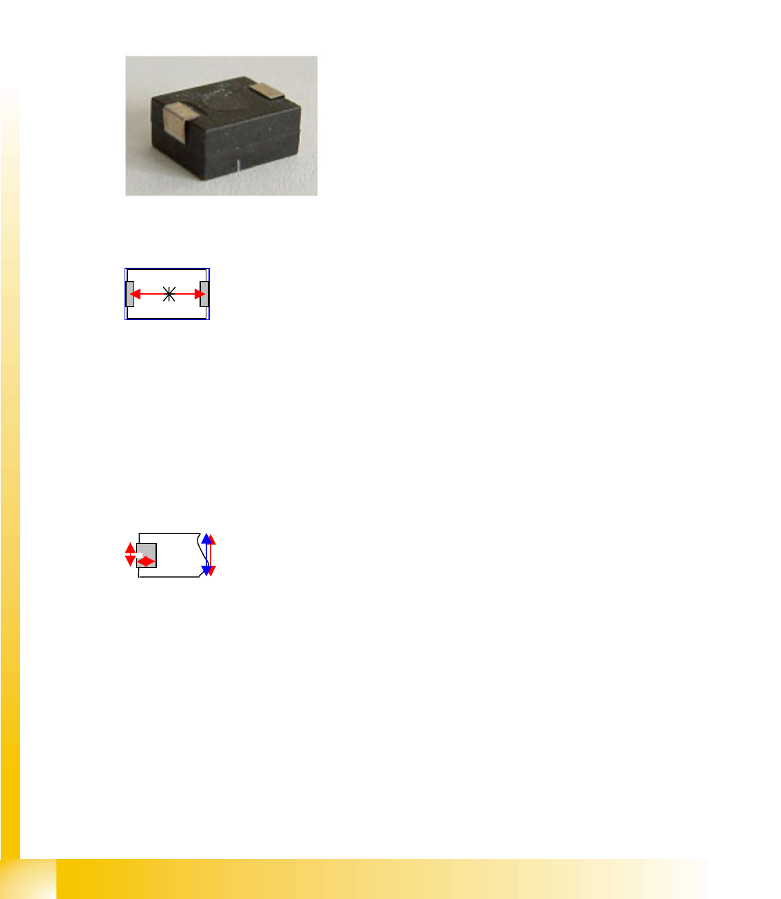
5.3.5 Moulded (Injection Moulded) Components (for Tantal Capacitors)
JEDEC description
JEDEC description
Lead description
Body description: rectangular.
The Z height of the body determines the measurable height
in the CO sensors.
The X/Y body dimensions determine the field of vision, the
Region of Interest.
This also determines the outer starting edge of the
Wraparound leads.
This component consists of two lead groups, each with one
lead.
The leads in the two groups must be identical!
The leads are inside the body surface.
In the case of this component, the leads are understood to
begin where the body begins, meaning that a group offset
does not need to be programmed. After optical centering,
the distance between the leads and the center (body
center) is measured and used for the placement
coordinates.
This component shape has so-called Wraparound leads,
which are wrapped around the component body, hence the
name Wraparound.
This defines the lead direction: towards the CO center. The
lead description requires definition of the lead length and
width.
The lead width is greater than the length, although they are
narrower than the body itself.
The lead length must not exceed 50 percent of the body
length (this would cause a short circuit!).
Make sure that no notches are programmed in the lead
surface (positive pole recognition).
Notches or dark areas in the leads could be interpreted as
"noise" in the lead surface of this CS. Alternatively, the CO
can be defined as a nonstandard component with notches.