MAN00000772_SI-G200BB_SVCPDFA.pdf - 第101页
Install Tray Unit (Including machine modification) SHEET 62/73 WKGB-10104-03 Installing Tray Unit (Including machine modification) [Adjustment of p ath line sensor] 1 Remove front cover of tray unit. 2 Store the tray p a…
Install Tray Unit (Including machine modification)
SHEET
61/73
WKGB-10104-03
Installing Tray Unit
(Including machine modification)
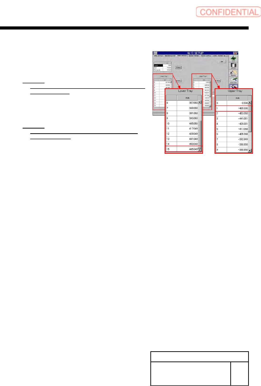
6 Calculate software limits on the VU axis
negative side and VL axis positive side.
1. Calculate a software limit value on the VU axis negative
side.
Equation:
VU axis negative side = VU axis supply position
No.501 - 4.0 [mm]
2. Calculate a software limit value on the VL axis positive
side.
Equation:
VL axis positive side = VU axis supply position
No.615 + 4.0 [mm]
7 Change value of software limit.
1. Open “c:¥asm¥mcdata2¥ac_param.ini” by word
pad.
2. Input the calculated value into
“SOFT_LIMIT_PLUS” and “SOFT_LIMIT_MINUS”
in [AC_VU].
3. Also input the calculated into “SOFT_LIMIT_PLUS”
and “SOFT_LIMIT_MINUS” in [AC_VL].
4. Overwrite and save
“c:¥asm¥mcdata2¥ac_param.ini” to restart the unit.
Install Tray Unit (Including machine modification)
SHEET
62/73
WKGB-10104-03
Installing Tray Unit
(Including machine modification)
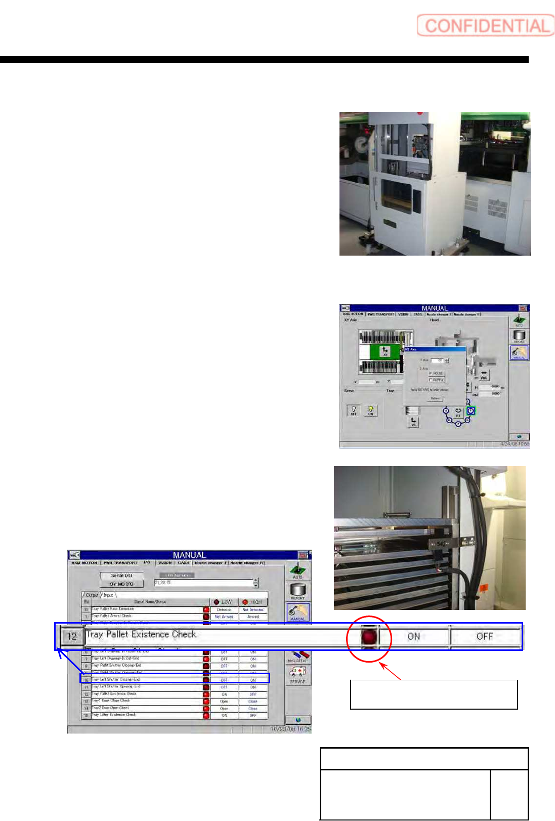
[Adjustment of path line sensor]
1 Remove front cover of tray unit.
2 Store the tray pallet into the Z501.
3 Move the VU axis to the Z501 by manual
operation.
4 Adjust sensor position, and check that it is
turned ON in the presence of tray pallet and
turned OFF in the absence of tray pallet.
5 Install the removed cover to the previous
state.
There is a palette :Light
There is not palette :Dark
I/O screen of Manual mode (Input 21,20 TI)
Install Tray Unit (Including machine modification)
SHEET
63/73
WKGB-10104-03
Installing Tray Unit
(Including machine modification)
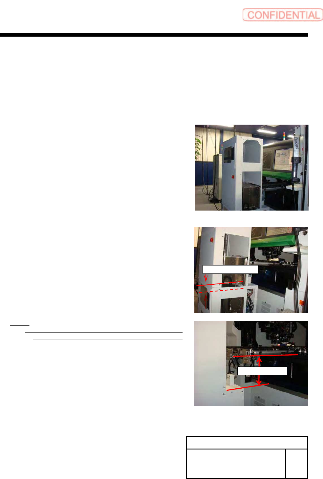
[Checking VU, VL closest reaching distance]
1 Return the unit to the origin.
2 Move the VU axis to the Z501 by manual V
axis operation.
3 Open the tray unit side cover.
4 Check that interval between the VU rack and
the VL rack is 41[mm] or more.
NOTE:
If this clearance is less than 41[mm], the relation of the
height between mounter and tray unit might be wrong.
In this case please set up again this height relation.
5 Install the removed side cover to the
previous state.
41[mm] or more
204±2[mm]