MAN00000772_SI-G200BB_SVCPDFA.pdf - 第333页
Adjustment HLGB-10415-01 Nozzle Sensor Adjus tment SHEET 1/7 Nozzle Sensor Adjustment [Necessary jigs] A Jig nozzle for nozzle changer B Nozzle (used in production) C Scale (about 300 mm) [Adjust the sensor att achment h…
Adjustment
HLGB-10414-01
Phase Adjustment for Nozzle
SHEET
7/7
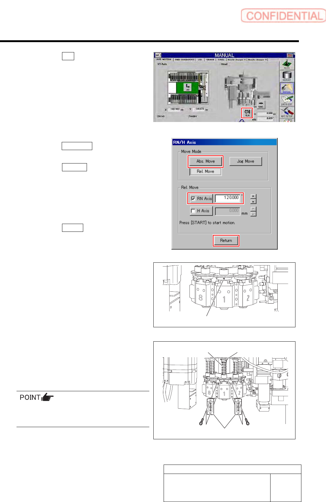
10. Click the R.H button on the AXIS
MOTION screen.
11. Click the Abs. Move button on the
RN/H-axis screen.
12. Click the RN-Axis button and input
“120” into the input space.
13. Press the [START] button on the
operation panel.
The RN axis absolute-moves to a position of
120°.
14. Click the Return button to close the
RN/H axis screen.
15. Tighten the sect screw (right) for the
small gear to 15[cN・m].
12 Install the spring and the spring holder to the
inner shaft.
13 Tighten the cap screws (2-CP3x10) to
40[cN・m] and install the mechanical valve.
Tighten 2-CP3x10 for fixing mechanical valve on
the upper and lower sides alternately little by
little.
14 Turn on the VACUUM breaker.
Set screw (Right)
Spring holder
Spring
Mechanical valve
Adjustment
HLGB-10415-01
Nozzle Sensor Adjustment
SHEET
1/7
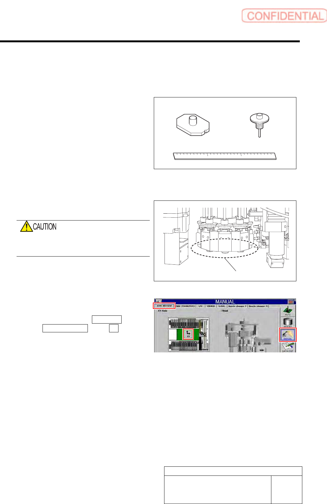
Nozzle Sensor Adjustment
[Necessary jigs]
A Jig nozzle for nozzle changer
B Nozzle (used in production)
C Scale (about 300 mm)
[Adjust the sensor attachment height]
1 Remove all nozzles from the head.
Do not execute the automatic replacement of
the nozzle when the teaching of the nozzle
changer has not been completed.
2 Move the head clear of the work area.
1. Click in an order of MANUAL menu
AXIS MOTION tab XY button.
XY Axis screen is displayed.
A
B
C
Remove all nozzles from the head.
Adjustment
HLGB-10415-01
Nozzle Sensor Adjustment
SHEET
2/7
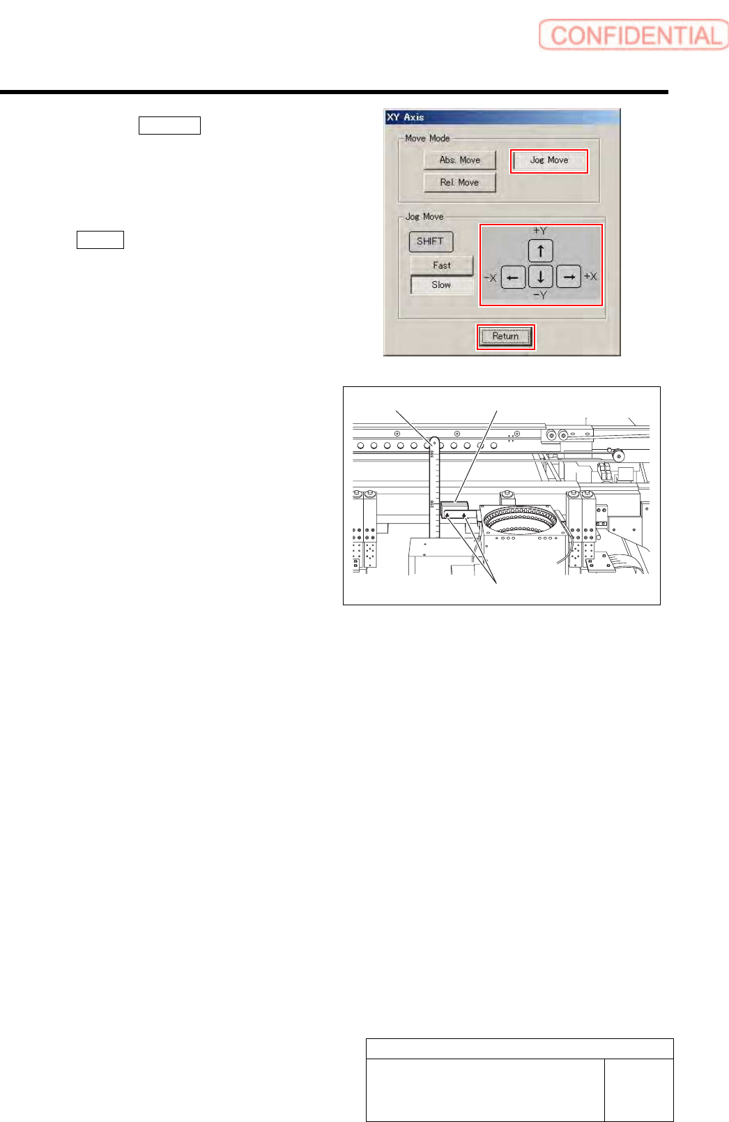
2. Click the Jog Move button.
3. Press the cursor key to move the head
to a position where working is easily
performed.
4. After moving the head, click the
Return button to close the XY Axis
screen.
3 Adjust detecting surface height of the nozzle
sensor (BS145, BS405) from upper face of
the stand.
1. Use a scale to measure detecting
surface height of the nozzle sensor
from upper face of the stand.
2. Loosen the installing bolts (2-CP2.5x8)
to adjust installing height of the nozzle
sensor so that the detecting surface
height becomes 203[mm].
3. After adjusting height, loosen the
installing bolts to fix the nozzle sensor.
4 Remove the scale and return the unit to the
origin.
Scale
Nozzle sensor
Installing bolts