MAN00000772_SI-G200BB_SVCPDFA.pdf - 第181页
Set-up HLGB-10204-01 PWB Camera Setup SHEET 1/4 PWB Camera Setup Perform this working on both heads on the front sid e and rear side. [Necessary jigs] • Thickness ga uge (t=1.0 mm) [Procedure] 1 Perform the origin positi…
Set-up
HLGB-10203-01
Acquiring Mounting Stroke Setup
SHEET
5/5
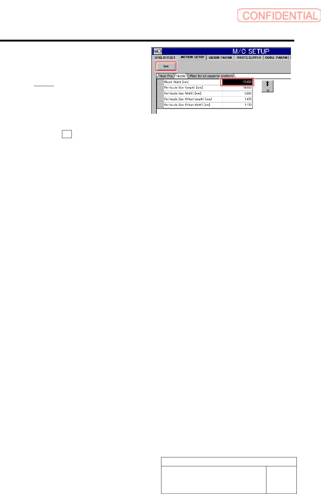
3. Input a value of 1/1000 of the value
described in calib.ini into the Mount
height.
Example:
Description of Calib.ini:
NOZZLE_S_TYPE_G=-23162
PWB mount height input value :-23.162
4. Press the Set button.
The inputted PWB fitted height is set.
10 When setting is ended, remove the
reference jig nozzle and calibration plate.
Set-up
HLGB-10204-01
PWB Camera Setup
SHEET
1/4
PWB Camera Setup
Perform this working on both heads on the front side and rear side.
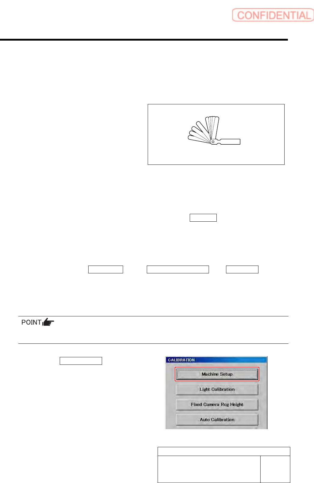
[Necessary jigs]
• Thickness gauge (t=1.0 mm)
[Procedure]
1 Perform the origin position return on the HI screen.
1. When the CALIBRATION screen is displayed, press the Complete button to return to the
HI screen.
2. Press the [ORG] button on the operation panel.
Origin position return is performed.
2 Display PWB Camera Setup screen.
1. Click in an order of M/C SETUP menuM/C MAINTENANCE tabCalibration button.
“Head at opposite position will be moved to noninterference area. Press the [START] button if you are really OK.”
is displayed on the message screen.
2. Press the [START] button on the operation panel.
CALIBRATION screen is displayed.
For procedures when selecting head for which calibration is performed, and when changing calibration jig,
refer to the “How to display calibration screen (HLGB-10105-01)”.
3. Click the Machine Setup button.
Machine Setup screen is displayed.
Thickness gauge
Set-up
HLGB-10204-01
PWB Camera Setup
SHEET
2/4
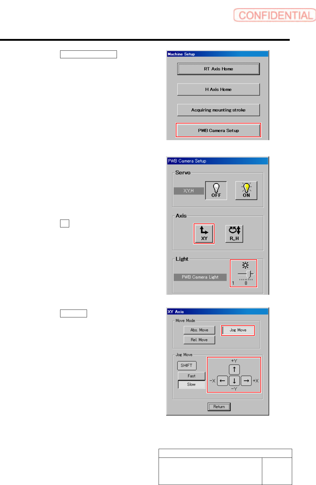
4. Click the PWB Camera Setup button
on the Machine Setup screen.
PWB Camera Setup screen is displayed.
3 Set brightness of the PWB camera light to
“6” or “7”.
4 Move the head to a position where the
transfer rail is displayed on the PCBOARD
DISPLAY screen.
1. Click the XY button on the PWB
Camera Setup screen.
XY Axis screen is displayed.
2. Click the Jog Move button.
3. Press the cursor key to jog-move the
head part onto the transfer rail.