MAN00000772_SI-G200BB_SVCPDFA.pdf - 第76页
Install Tray Unit (Including machine modification) SHEET 37/73 WKGB-10104-03 Installing Tray Unit (Including machine modification) [Change of machine dat a (change of specification from tray specification to tray specifi…
Install Tray Unit (Including machine modification)
SHEET
36/73
WKGB-10104-03
Installing Tray Unit
(Including machine modification)
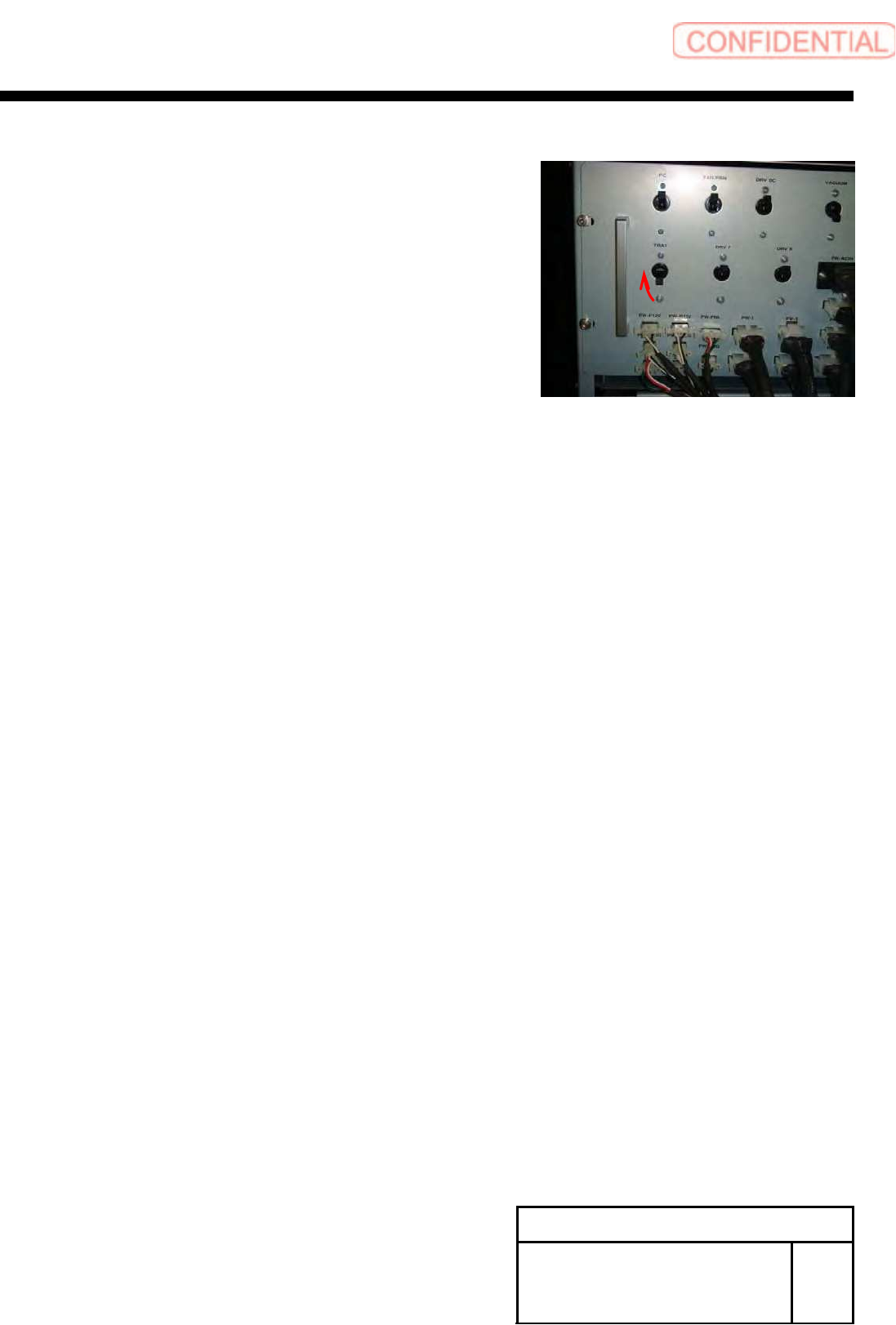
3 Turn ON the TRAY breaker for the rear
power unit.
Install Tray Unit (Including machine modification)
SHEET
37/73
WKGB-10104-03
Installing Tray Unit
(Including machine modification)
[Change of machine data (change of specification from tray specification to
tray specification)]
1 Turn ON power for the unit and open the
explorer.
NOTE:
It is unnecessary to perform axis operation
such as origin return after start of mounted
machine.
2 Open
the ”c:¥asm¥mcdata2¥asmconfig.ini” by
word pad.
3 Change the values of “TRAY_UNIT_L”
and “TRAY_UNIT_R” for [Supply] to “1.”
4 Change the value of “CART_UNIT_F”
and“CART_UNIT_F” for [Supply] to “0.”
5 Restart the mounted machine.
SHEET
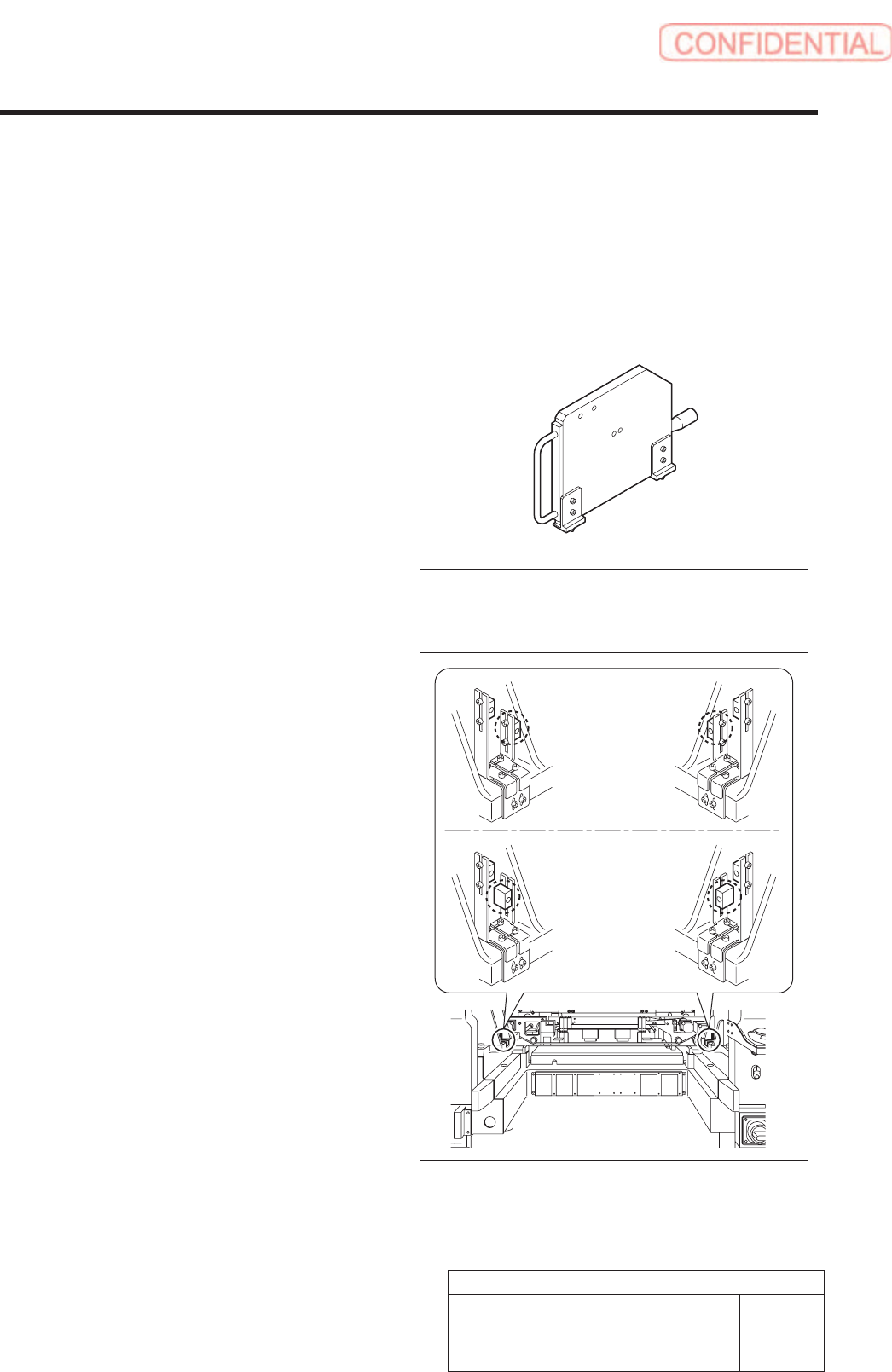
Supply section of cassette specification is different from that of tray specification in optical axis
position of area sensor. Be careful of sensor mounting position and hole position for jig before
carrying out optical axis adjustment.
[Necessary jigs]
• Optical axis adjustment jig
[Procedure]
1. Check area sensor mounting position.
Cassette specification is different from tray
specification in area sensor mounting method.
Check that the area sensor is mounted so as to be
suitable for the specification.
Optical axis adjustment jig
Cassette
specification
Tray specification
Install Tray Unit (Including machine modification)
38/73
WKGB-10104-03
Installing Tray Unit
(Including machine modification)
[Area Sensor Optical Axis Adjustment]