MAN00000772_SI-G200BB_SVCPDFA.pdf - 第665页
Ch ange Procedu re for H ead U n i t 10 Fit the remov ed he ad unit into t he to p frame on the head blo c k, and fasten the scr ews 4- C6x20 fo r loc king. [Reassembl y] 11 Match the ho le s in the ne w head unit and th…
Change Procedure for Head Unit
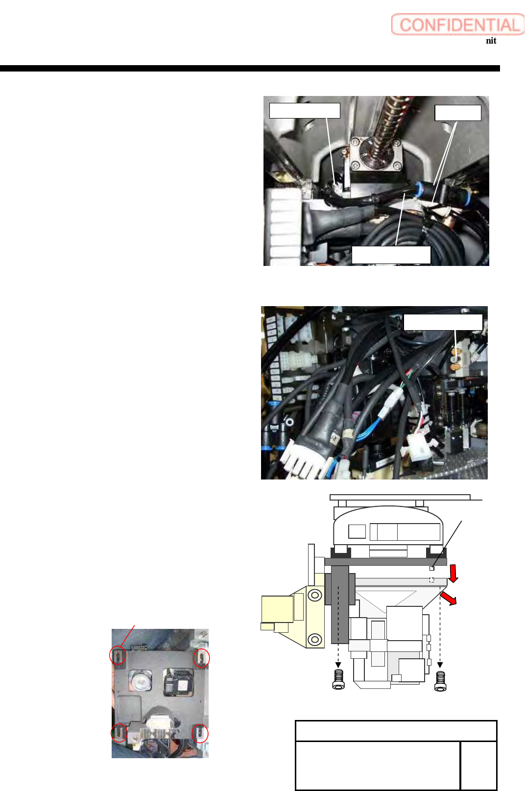
7 Pull out the air tubes (D6 and D8)(2pcs) from the Joint.
Attention
Mark it before pulling out a tube.
8 Pull out the air tube (D6 )from the Valve.
Attention
Mark it before pulling out a tube.
9 Remove the screws 4-C6x20,and pull out the head
unit from the parallel pin.
Attention
As the head unit is heavy, carefully hold the
head unit while working.
Move the head unit in the direction of the arrow
and remove.
Be careful to the lose of the spacer.
Change Procedure for Head
Unit
RPGB-10301-1
SEET
2/4
Valve
manifold
air tubes
Joint
Parallel pin
C6x20
Spacer
Change Procedure for Head Unit
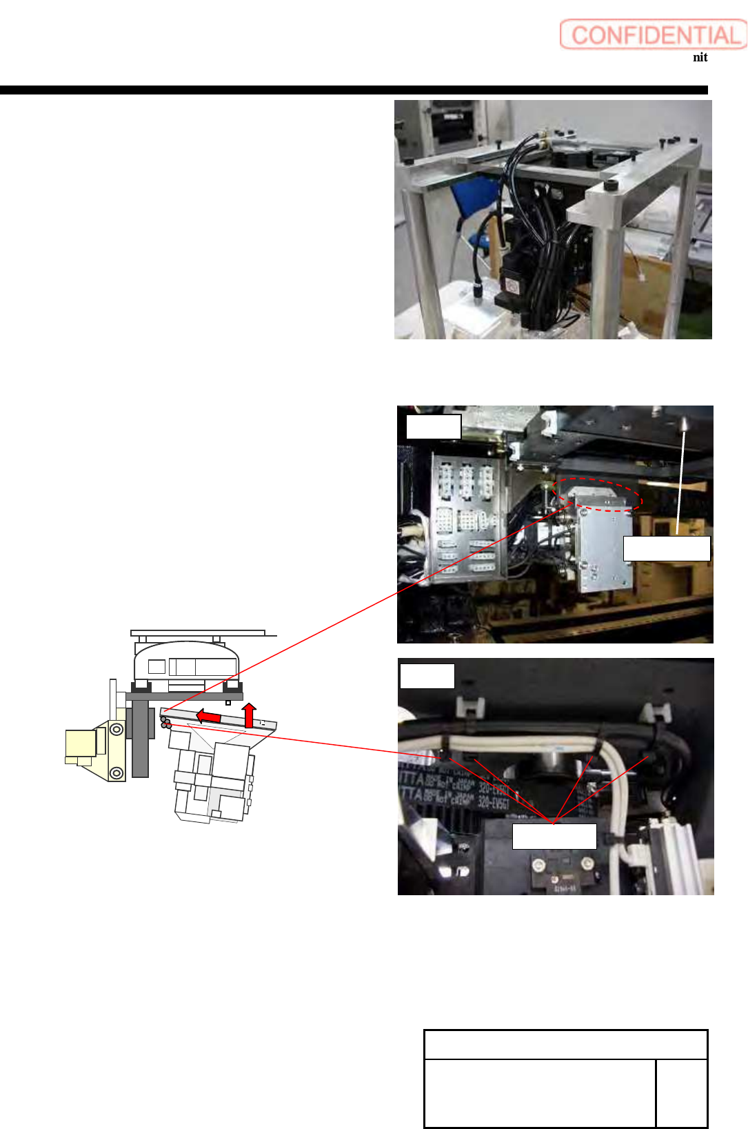
10 Fit the removed head unit into the top frame on
the head block, and fasten the screws 4-C6x20
for locking.
[Reassembly]
11 Match the holes in the new head unit and the
parallel pins, And fasten the screws 4-C6x20 for
locking.
Point
Make sure the cable tie of direction.
Refer to Fig2
Change Procedure for Head
Unit
RPGB-10301-1
SEET
3/4
Parallel Pins
Cable tie
Fig2
Fig1
Change Procedure for Head Unit
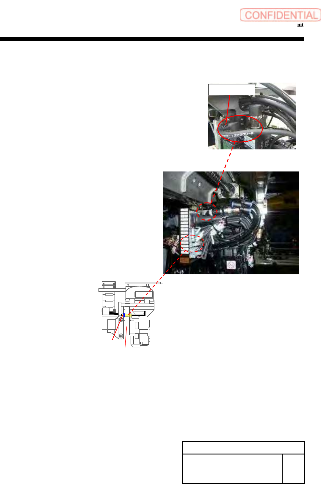
12 Connect the air tubes (D6 and D8)(2 pcs) to the
Union elbows of the manifold.
13 Connect the air tube of D4 to the solenoid valve.
14 Connect all the removed connectors, and lock the wiring
with the cable tie not to allow the wiring to interfere
with the movable parts..
1. Connector of the PWB camera (CAME1).
2. Connectors connected through the connector panel.
(HM,RTM,RNM,CSFT,FSEN2,LED,PD,CSFT-LS,HE,
RTE,RNE,VAC-2,RTS,RNS)
3. Connector of the parts camera.. (CAME2)
4. Connector connected through the head
connector panel of HLSB and PD-LSB
(BS-NZL,PDLS-3,PDLS-4,HLS-2,HLS-3,HLS-4)
5. Connector of the rotary encoder. (DE1)
POINT
Connect the cable of pick up camera
to keep the slack.
Connect the connector of DE1 in the interior
of the connector panel.
15Turn on the main power and the air main cock.
[Adjustment]
16 Calibration
1.HLGB-10101-01 Preparation for calibration
2.HLGB-10201-01 Machine setup
3.HLGB-10301-01 Calibration
Change Procedure for Head
Unit
RPGB-10301-1
SEET
4/4
DE1
Connector panel
Pick Up Camera