MAN00000772_SI-G200BB_SVCPDFA.pdf - 第99页
Install Tray Unit (Including machine modification) SHEET 60/73 WKGB-10104-03 Installing Tray Unit (Including machine modification) 3. Release the emergency st op and return the unit to the origin. NOTE: While turning OFF…
Install Tray Unit (Including machine modification)
SHEET
59/73
WKGB-10104-03
Installing Tray Unit
(Including machine modification)
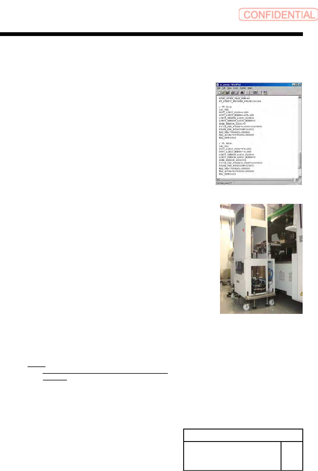
[V axis software limit setup]
1 Temporarily expand a value of the software limit.
1. Open “c:¥asm¥mcdata2¥ac_param.ini” by word pad.
2. Add an absolute value 100 to “SOFT_LIMIT_PLUS” and
”SOFT_LIMIT_MINUS” in [AC_VU] respectively.
3. Add an absolute value 100 to “SOFT_LIMIT_PLUS” and
“SOFT_LIMIT_MINUS” in [AC_VL] respectively.
4. Overwrite and save “c:¥asm¥mcdata2¥ac_param.ini”
and restart the unit.
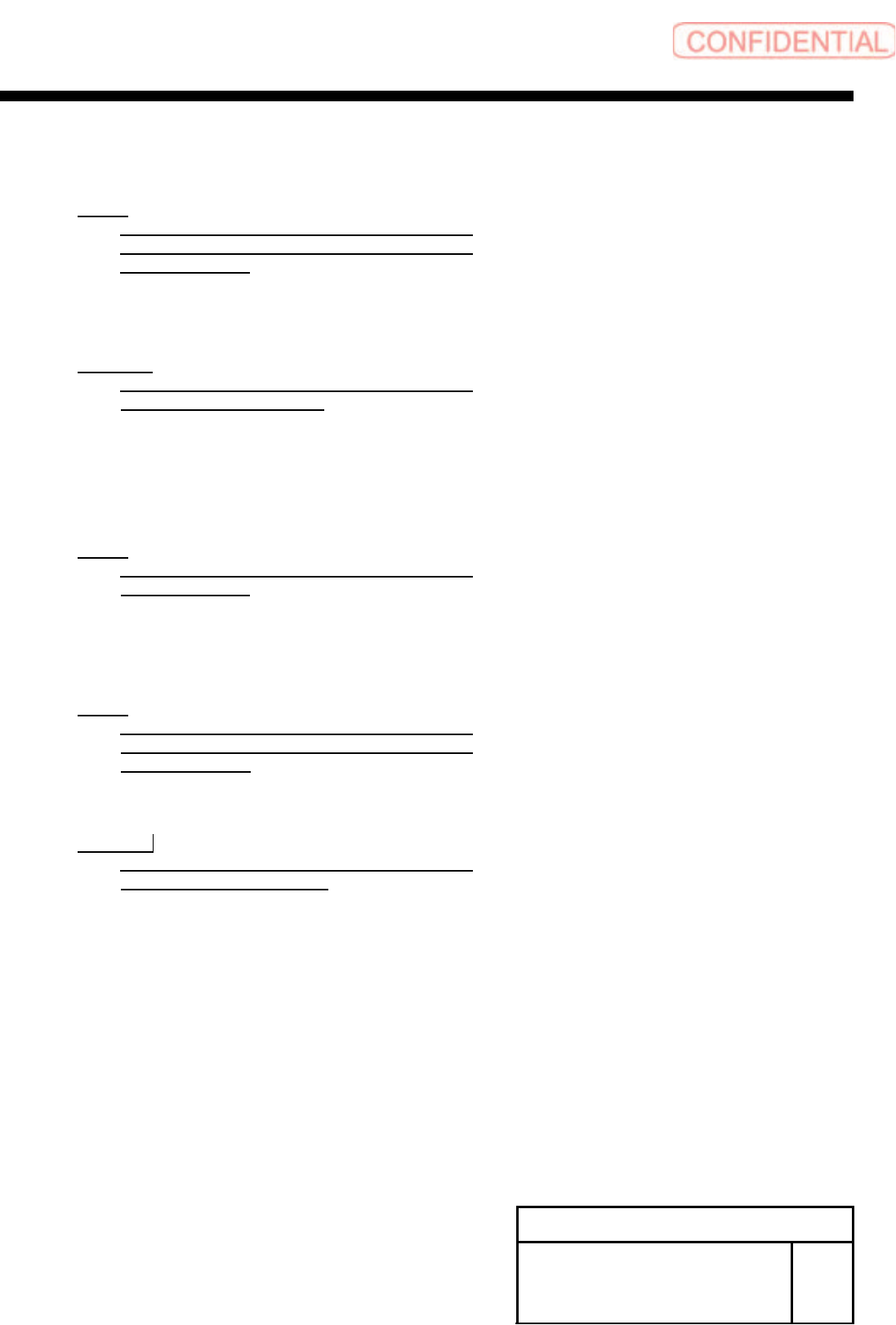
2 Remove the tray unit side cover of upper
and lower.
3 Return the unit to the origin.
4 Check position of the VU axis positive side
OT sensor.
1. Manually move the VU axis upward by JOG.
NOTE:
Move it by JOG every time while checking the
position.
2. Check the position of the UV axis immediately
before emergency stop.
Install Tray Unit (Including machine modification)
SHEET
60/73
WKGB-10104-03
Installing Tray Unit
(Including machine modification)
3. Release the emergency stop and return the unit to
the origin.
NOTE:
While turning OFF the brake for the VU axis,
manually move the tray rack to release the
emergency stop.
4. Calculate the VU axis software limit value.
Equation:
VU axis positive side software limit = OT
sensor position - 1.5 [mm]
5 Check position of the VL axis negative side
OT sensor.
1. Manually move the VL axis downward by JOG.
NOTE:
Move it by JOG every time while checking the
VL axis position.
2. Check the position of the VL axis immediately before emergency stop.
3. Release the emergency stop and return the unit to the origin.
NOTE:
While turning OFF the brake for the VL axis,
manually move the tray rack to release the
emergency stop.
4. Calculate the VL axis software limit value.
Equation:
VL axis negative side software limit = OT
sensor position + 1.5 [mm]
Install Tray Unit (Including machine modification)
SHEET
61/73
WKGB-10104-03
Installing Tray Unit
(Including machine modification)
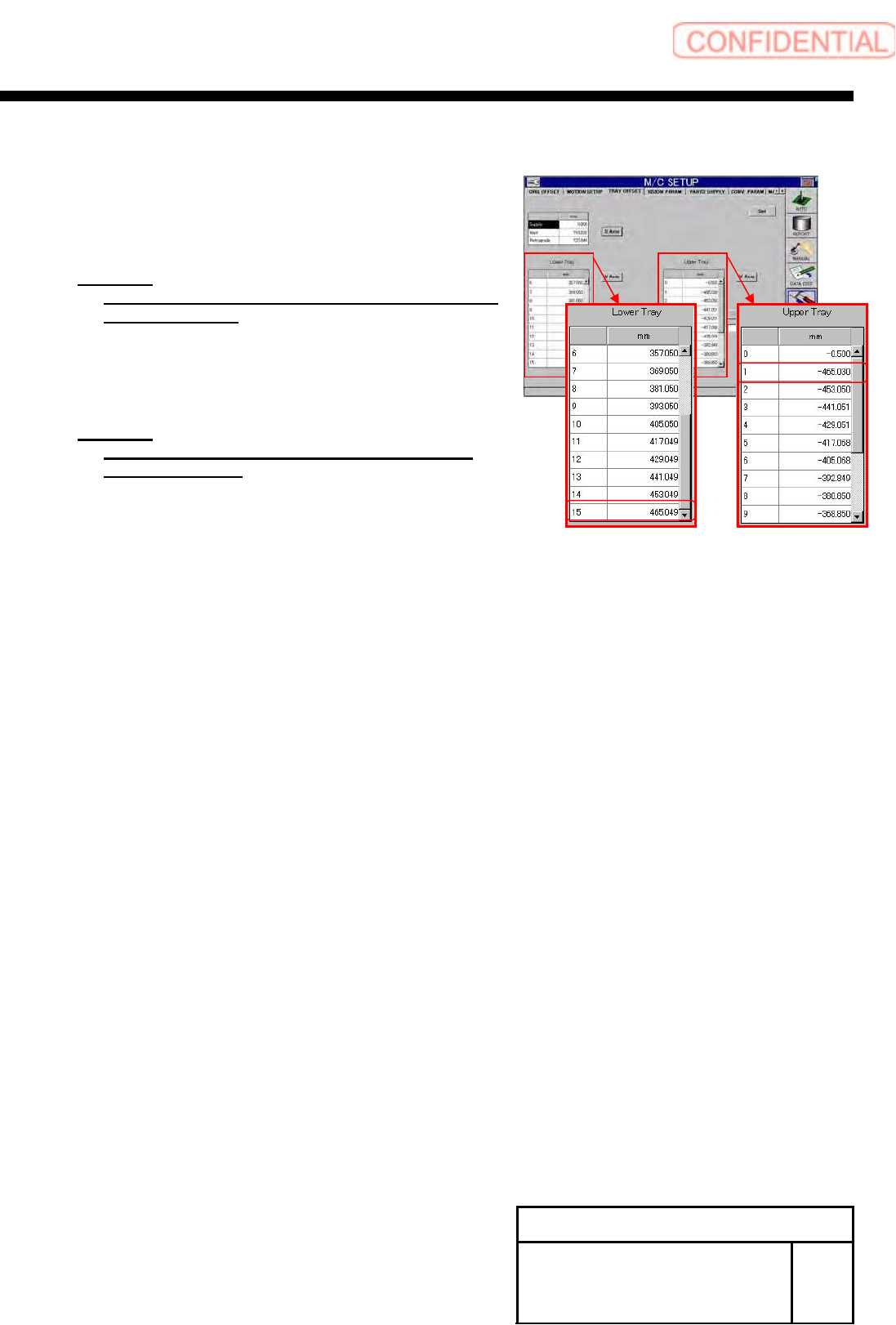
6 Calculate software limits on the VU axis
negative side and VL axis positive side.
1. Calculate a software limit value on the VU axis negative
side.
Equation:
VU axis negative side = VU axis supply position
No.501 - 4.0 [mm]
2. Calculate a software limit value on the VL axis positive
side.
Equation:
VL axis positive side = VU axis supply position
No.615 + 4.0 [mm]
7 Change value of software limit.
1. Open “c:¥asm¥mcdata2¥ac_param.ini” by word
pad.
2. Input the calculated value into
“SOFT_LIMIT_PLUS” and “SOFT_LIMIT_MINUS”
in [AC_VU].
3. Also input the calculated into “SOFT_LIMIT_PLUS”
and “SOFT_LIMIT_MINUS” in [AC_VL].
4. Overwrite and save
“c:¥asm¥mcdata2¥ac_param.ini” to restart the unit.