MAN00000772_SI-G200BB_SVCPDFA.pdf - 第61页
Install Tray Unit (Including machine modification) SHEET 22/73 WKGB-10104-03 Installing Tray Unit (Including machine modification) [Inst allation of cassette t able and cassette floating detection sensor] 1 Pull out 375 …
Install Tray Unit (Including machine modification)
SHEET
21/73
WKGB-10104-03
Installing Tray Unit
(Including machine modification)
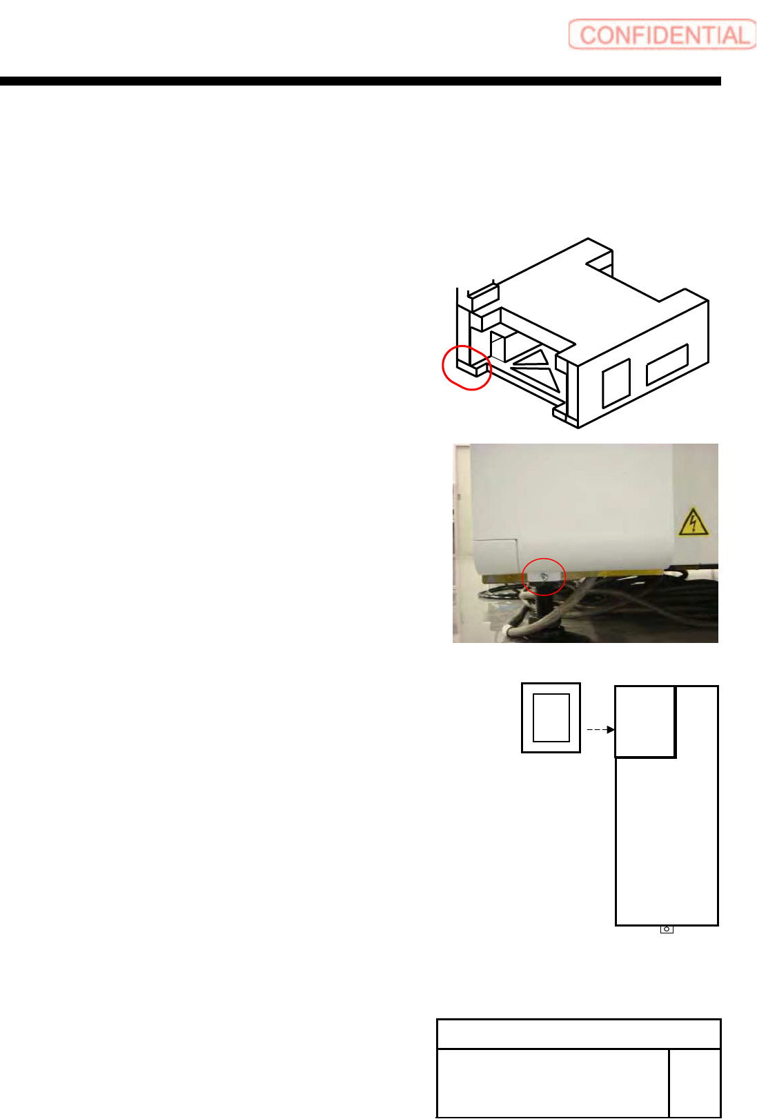
[Change in shape and installation of right lower rear cover]
1 Loosen the +T4x8 to remove the right
lower rear cover.
2 Loosen the 3-CP4x6 to remove the cover
(standard) for joint.
3 Install the cover (tray specification) for
joint with the 3-CP4x6.
Rear
Install Tray Unit (Including machine modification)
SHEET
22/73
WKGB-10104-03
Installing Tray Unit
(Including machine modification)
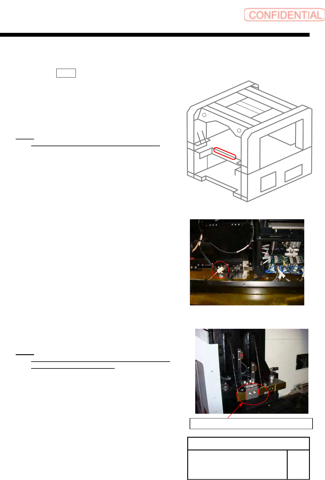
[Installation of cassette table and cassette floating detection sensor]
1 Pull out 375 on the connector wired
on the back of the shoot bracket, and
move it near the center of the shoot
bracket.
NOTE:
After working, bind the wires with INSULOCK.
2 Mark the installing position of the area
sensor bracket.
NOTE:
Mark the installing positions of both of the right
and left area sensor brackets.
Mark end section of the bracket.
REAR
Install Tray Unit (Including machine modification)
SHEET
23/73
WKGB-10104-03
Installing Tray Unit
(Including machine modification)
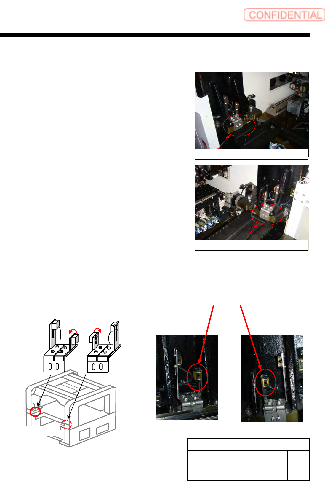
3 Loosen the 2-CP4x8 to remove the area
sensor.
4 Fix the cassette table with the
4-CP10x40.
5 Install the area sensor to the previous position.
1.
Replace Beam sensor as shown in the figure below (364DT, 364DR) .
Sensor bracket on right side
Sensor bracket on left side
BL
BR
364UT
364DT
364UR
364DR
(Rear)