MAN00000772_SI-G200BB_SVCPDFA.pdf - 第616页
1. Functions of the Multifunctiona l Mounter TFGB-10101-0 1 SI-G200 (B Head) Overview SHEET 1/20 SI-G200 (B Head) Overview SI-G200, chi p parts mounte r , has two hea ds installed on it. This mounter has newly designed m…


1. Functions of the Multifunctional Mounter
TFGB-10101-01
SI-G200 (B Head) Overview
SHEET
1/20
SI-G200 (B Head) Overview
SI-G200, chip parts mounter, has two heads installed on it.
This mounter has newly designed multifunctional heads in order to deal with the larger scope of parts, such as
odd-shaped ones. The configuration of this mounter’s control system for controlling its heads is the same as that
of SI-G200 (high-speed mounter).
This document explains the functions and features of SI-G200 (multifunctional mounter).
1. Functions of the Multifunctional Mounter
The multifunctional mounter has eight nozzles per head and can manufacture parts with dimensions of 1005 to
100 x 50 mm and a height of up to 13 mm. Described below are the features of the mounter for picking up,
recognizing, and mounting parts.
2. Features of the Mounter
Described below is the configuration of SI-G200 multifunctional mounter.
Head configuration : 2 heads (eight nozzles per head)
Recognition camera : PWB camera, pickup check camera, and fixed camera (wide and narrow
fields of view)
Supply section : 40 cassettes at the front and 40 cassettes at the rear (when converted into
8-mm cassettes)
Recognition method : Individual recognition, global recognition, and split recognition
Image processing method : Reflection recognition (Transmission recognition is not supported.)
Parts mounting : Normal mode and high-Accuracy mode
Nozzle changer : 8 changers x 3 sets per head
Options
Tray changer : 15 tray changers x 2
Tray changers can be installed only on the rear head.
When the tray changer option is selected, the number of cassettes to be
mounted is seventeen.
(when converted into 8-mm cassettes)
POP unit :
Accuracy-improving function kit:
Adhesion and missing part detecting function:
3. Sizes of Parts That Can Be Handled
TFGB-10101-01
SI-G200 (B Head) Overview
SHEET
2/20
3. Sizes of Parts That Can Be Handled
There are restrictive conditions between camera types/lighting methods and parts. Select an appropriate camera
and a recognition method according to the size of parts or the shape and size of electrodes.
Parts may not be recognized correctly, depending on the shape of electrodes or the degree of reflection. In such a
case, take measures, such as switching a camera to use to another.
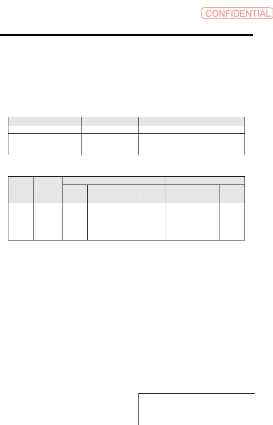
Camera Types, Recognition Methods, and Sizes of Parts to Be Handled
Cameras (Field of View) Recognition Methods Sizes of Parts to Be Handled
Fixed camera (Large view) Global recognition 1005 to □10mm
Fixed camera (Large view) Individual recognition
to □50mm
(split recognition: up to 100 x 50 mm)
Fixed camera (Small view) Individual recognition 1005 to □18mm
Difference in the Sizes of Target Electrodes According to Camera Types
Lead part BGA part
Camera
Recognition
Method
Lead
Width
(mm)
Space
between
Leads (mm)
Pitch
(mm)
Ground
Plane
(mm)
Ball
Diameter
(mm)
Space
between
Balls (mm)
Pitch
(mm)
Large view
Global
recognition
Individual
recognition
0.20 or
more
0.30 or more
0.50 or
more
0.24 or
more
0.40 or more
0.32 or
more
0.72 or
more
Small view
Individual
recognition.
0.10 or
more
0.15 or more
0.25 or
more
0.10 or
more
0.16 or more
0.12 or
more
0.28 or
more