MAN00000772_SI-G200BB_SVCPDFA.pdf - 第363页
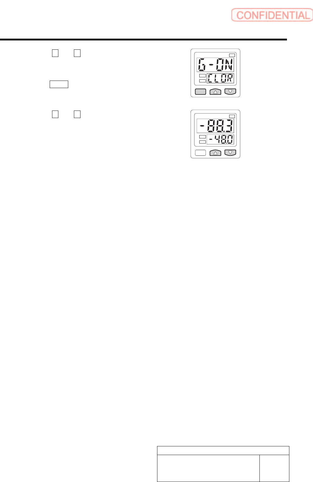
Adjustment HLGB-10423-01 V acuum Pump Se nsor Setup SHEET 2/2 6 Press the U and V button to display the G-ON. 7 Press the MODE button one time. 1 kPa 2 8 Press the U and V button to display the -48.0. Setting is complete…
Adjustment
HLGB-10423-01
Vacuum Pump Sensor Setup
SHEET
1/2
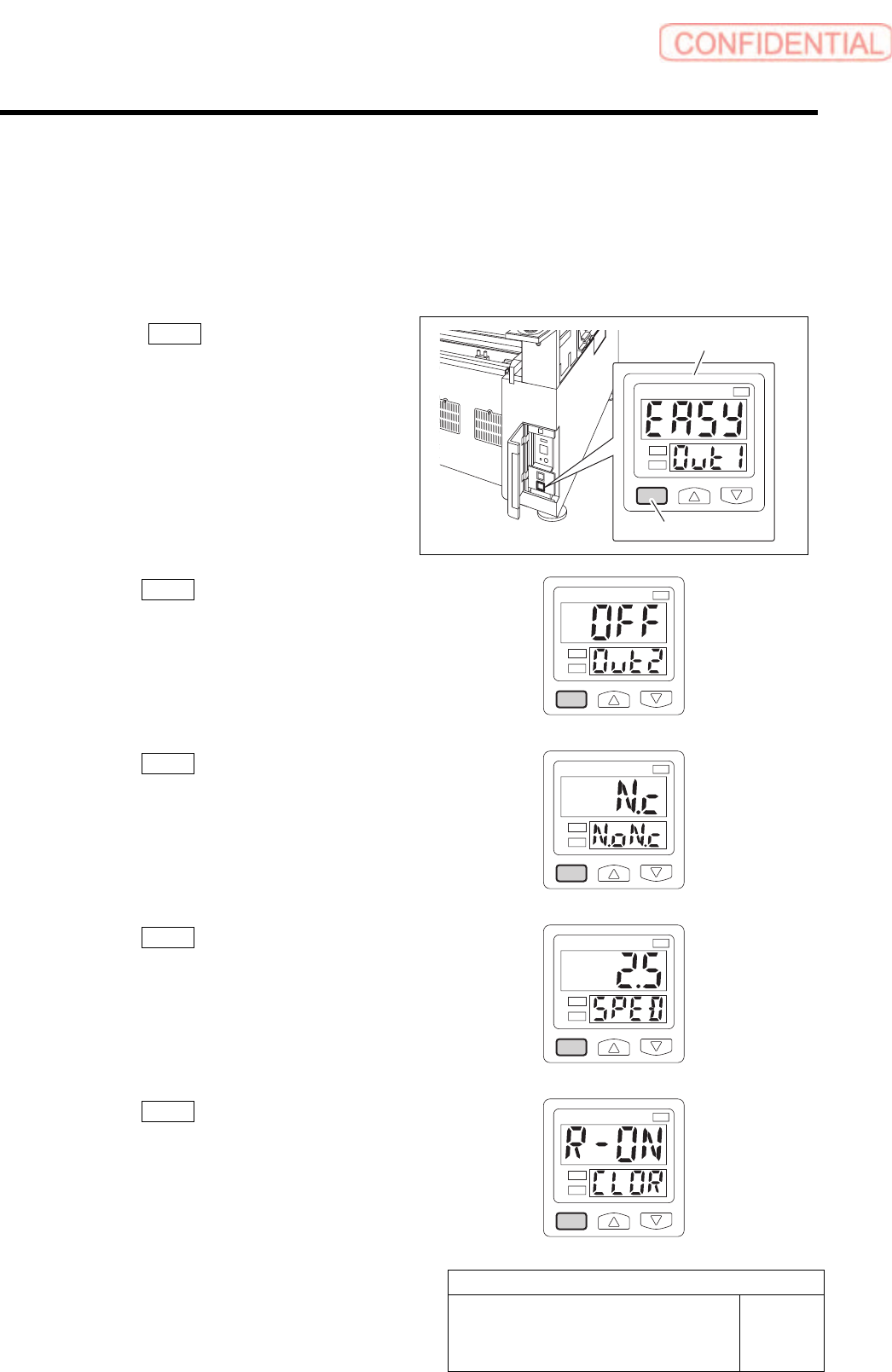
Vacuum Pump Sensor Setup
This section describes setting procedure for the Vacuum Pump sensor located on the on the interface
panel on the back of the unit.
[Procedure]
1 Press the MODE button for longer than 2
seconds.
EASY on the display screen.
1
kPa
2
2 Press the MODE button one time.
OFF on the display screen.
1
kPa
2
3 Press the MODE button one time.
N.c on the display screen.
1
kPa
2
4 Press the MODE button one time.
2.5 on the display screen.
1
kPa
2
5 Press the MODE button one time.
R-ON on the display screen.
1
kPa
2
Vacuum Pump sensor
MODE button
Adjustment
HLGB-10423-01
Vacuum Pump Sensor Setup
SHEET
2/2
6 Press the U and V button to display the
G-ON.
7 Press the MODE button one time.
1
kPa
2
8 Press the U and V button to display the
-48.0.
Setting is completed.
1
kPa
2
Adjustment
HLGB-10424-01
Supplied Air Sensor Setup
SHEET
1/2
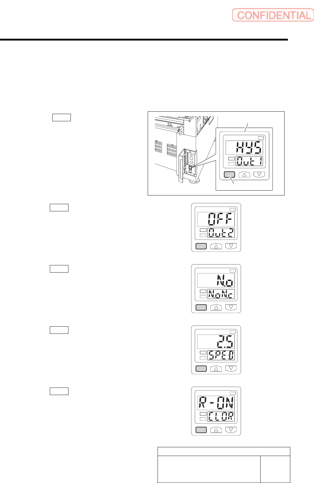
Supplied Air Sensor Setup
This section describes setting procedure for the Supplied Air sensor located on the on the interface
panel on the back of the unit.
[Procedure]
1 Press the MODE button for longer than 2
seconds.
HYS on the display screen.
1
kPa
2
2 Press the MODE button one time.
OFF on the display screen.
1
kPa
2
3 Press the MODE button one time.
N.o on the display screen.
1
kPa
2
4 Press the MODE button one time.
2.5 on the display screen.
1
kPa
2
5 Press the MODE button one time.
R-ON on the display screen.
1
kPa
2
Supplied air sensor
MODE button