MAN00000772_SI-G200BB_SVCPDFA.pdf - 第257页
Calibration HLGB-10312-01 Checking Pickup Positio n SHEET 4/4 7 Subsequently , check pickup pos ition at positions of Z120 、 Z140. 1. Move the pickup point jig to the position of Z12 0 or Z140. 2. Click #2 or #3 . 3. Cli…
Calibration
HLGB-10312-01
Checking Pickup Position
SHEET
3/4
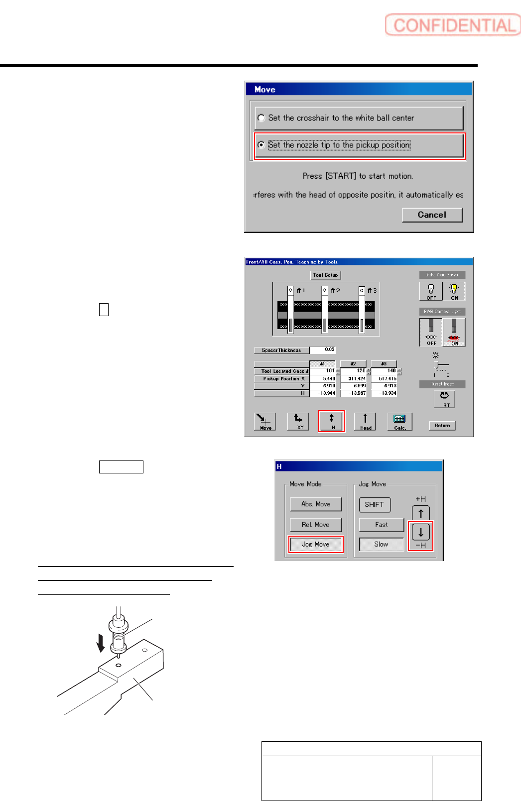
5 Put check mark on the “Move nozzle end to
pickup position” and press the [START]
button on the operation panel.
The length reference nozzle jig moves to above the
hole in front of the pickup point jig.
6 Check that end of the length reference
nozzle jig is smoothly inserted into the hole
in front of the pickup point jig.
1. Click the H button on the front and
cassette position whole teaching
screen.
H screen is displayed.
2. Click the Jog Move button.
3. Press the lower cursor key to check
end of the length reference nozzle jig is
smoothly inserted into the hole in
front of the pickup point jig.
If the end of the length reference nozzle jig is not
smoothly inserted, perform “Pickup position
setup” in the previous item again.
Pickup point Jig
Length reference
nozzle jig
Calibration
HLGB-10312-01
Checking Pickup Position
SHEET
4/4
7 Subsequently, check pickup position at positions of Z120、Z140.
1. Move the pickup point jig to the position of Z120 or Z140.
2. Click #2 or #3.
3. Click the Move button.
Move screen is displayed.
4. Check pickup position at the positions of Z120, Z140 by the same procedure as the
procedure 5-6.
If the end of the length reference nozzle jig is not smoothly inserted, perform “Pickup position setup” in the
previous item again.
8 When “Pickup position setup” and “Checking pickup position” on the front, also perform the “Pickup
position setup” and “Checking pickup position” on the rear in the same way.
Calibration
HLGB-10313-01
Mount Accuracy Calibration
SHEET
1/11
Mount Accuracy Calibration
By recognizing the mounted part position with the PWB camera, this system can calculate the
correction value and calibrate the mount position. When the pickup position is unstable, the stability
of the mounting accuracy may not be assured. Before applying the calculated correction value,
execute the test mounting two or three cycles.
There are two calibration modes: “Transcription calibration” and “Batch recognition calibration”. Be
sure to execute the batch recognition calibration after executing the transcription calibration.
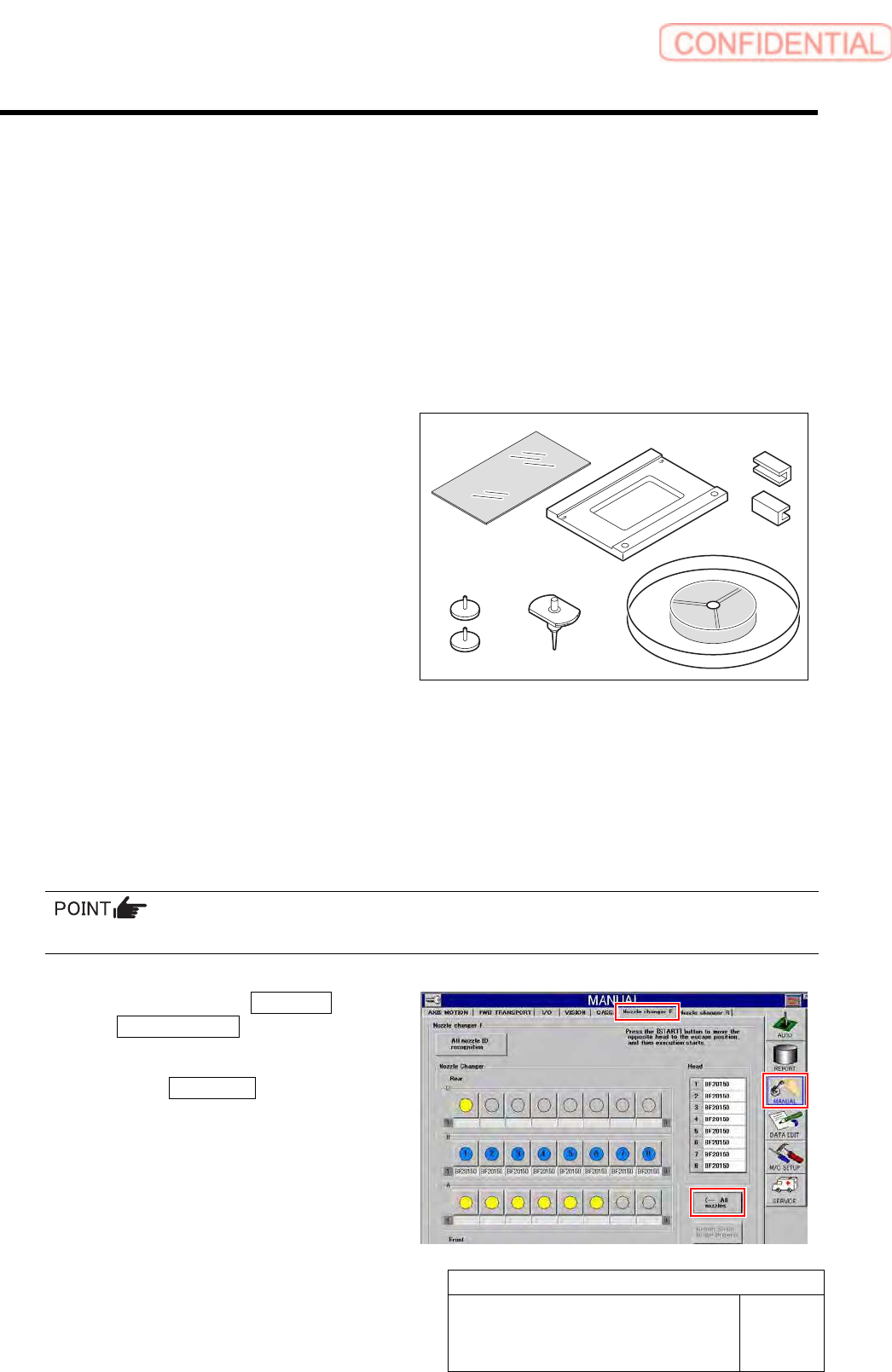
[Necessary jigs]
A Glass PWB for easy measurement
(Accuracy improvement function kit)
B Glass PWB frame for easy measurement
(Accuracy improvement function kit)
C Clamp (Accuracy improvement function
kit)
D Knurled knob with pad (Accuracy
improvement function kit)
E BF1305R nozzle (8 pcs.)
F Mounting accuracy correction jig 1005C
chip (3-276-548-01)
G Parts cassette GAK0802/P100
H Double-stick tape
[Preparation before work]
1 Switch the USER LEVEL to SERVICE.
For change procedure on user level, refer to the “Change on user level [HLGB-10104-01].”
2 Collect all the nozzles for production.
When BF1305R nozzles are attached to all the Indexes, this step is not required.
1. Click in an order of MANUAL menu
Nozzle changer tab.
Nozzle Changer screen is displayed.
2. Click the All nozzles button.
All nozzles installed on the head are returned to
the nozzle cartridge.
A
B C
DE
F