MAN00000772_SI-G200BB_SVCPDFA.pdf - 第270页
Calibration HLGB-10314-01 XY A xis Sof tware Limit Setup SHEET 2/1 1 3. Uncheck “Read-only” on t he Properties window of the ac_p aram.ini file. 4. Click the OK button. 4 Change values in the ac_p aram.ini file for the f…
Calibration
HLGB-10314-01
XY Axis Software Limit Setup
SHEET
1/11
XY Axis Software Limit Setup
[Setup procedure]
1 Use the following calculating equations to carry out coordinate calculation of software limit for each
axis.
Front side X-Axis
SOFT_LIMIT_PLUS=(X coordinate of front Z101) +798.7
SOFT_LIMIT_MINUS=(X coordinate of front Z101) +69.7
Front side Y-Axis
SOFT_LIMIT_PLUS=(Y coordinate of front Z101) +653.9
SOFT_LIMIT_MINUS=(Y coordinate of front Z101) -26.8
Rear side X-Axis
SOFT_LIMIT_PLUS=(X coordinate of rear Z101) -73.8
SOFT_LIMIT_MINUS=(X coordinate of rear Z101) -802.7
Rear side Y-Axis
SOFT_LIMIT_PLUS=(Y coordinate of rear Z101) +26.7
SOFT_LIMIT_MINUS=(Y coordinate of rear Z101) -653.7
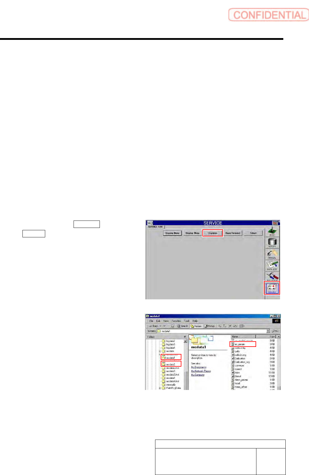
2 Click in an order of SERVICE menu
Explorer button.
Explorer screen is displayed.
3 Put ac_param.ini file for front side and rear
side into a rewritable status.
1. For the front side, open Properties
window for ac_param.ini file in
C:¥asm¥mcdata1.
2. For the rear side, open Properties
window for ac_param.ini file in
C:¥asm¥mcdata2.
Right-click the file and select “Properties” from
the shortcut menu to open the Properties window.
Calibration
HLGB-10314-01
XY Axis Software Limit Setup
SHEET
2/11
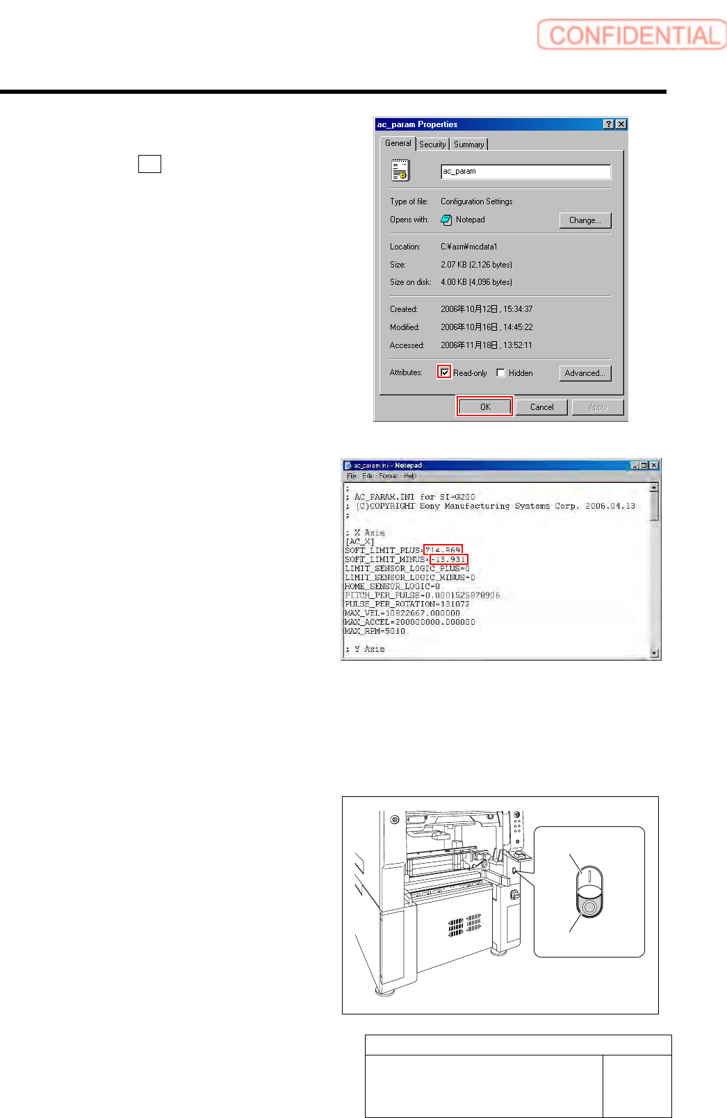
3. Uncheck “Read-only” on the Properties
window of the ac_param.ini file.
4. Click the OK button.
4 Change values in the ac_param.ini file for
the front and rear sides.
1. Open Notepad by the ac_param.ini
file.
2. Input the values calculated in the
procedure 1 into spaces of
“SOFT_LIMIT_PLUS” and
“SOFT_LIMIT_MINUS” of [AC_X].
3. Similarly, input the values calculated
in the procedure 1 into spaces of
“SOFT_LIMIT_PLUS” and
“SOFT_LIMIT_MINUS” of [AC_Y].
4. Save the ac_param.ini file and end.
5. Open the Properties window of the
ac_param.ini file, and check the
“Read-only”.
5 Re-start the unit.
1. Close the explorer window.
2. Press the power off switch.
Shutting down of the system starts and the power
is automatically shut off.
3. Press the power on switch.
The system starts, and the set value is reflected
on the equipment.
Power on switch
Power off switch
Calibration
HLGB-10314-01
XY Axis Software Limit Setup
SHEET
3/11
[Front side software limit checking procedure]
1 Check X coordinate of the software limit
sensor in X axis negative direction.
1. Press the [ORG] button on the
operation panel to perform origin
position return.
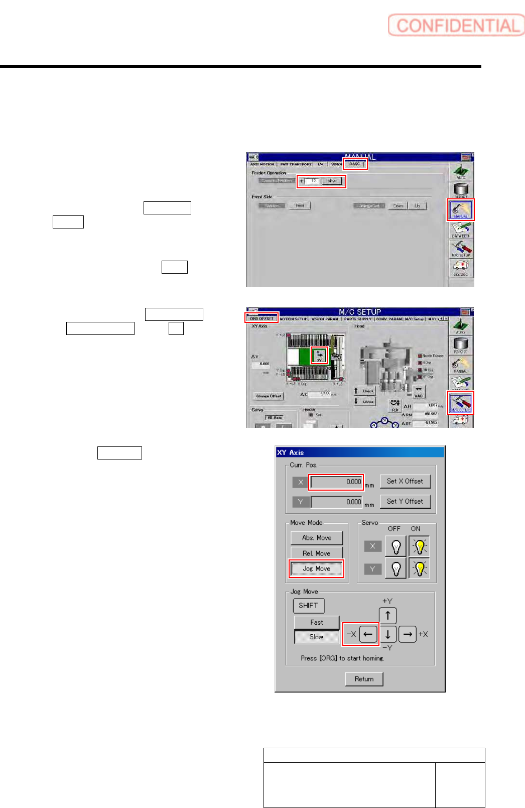
2. Click in an order of MANUAL menu
CASS. tab.
Cassette operation screen is displayed.
3. Input “101” into the cassette position
input box and click the Move button.
The head moves to the cassette position “101”.
4. Click in an order of M/C SETUP menu
ORG OFFSET tab XY button.
XY Axis screen is displayed.
5. Click the Jog Move button.
6. Press the left cursor to jog-move X axis
in negative direction.
When X axis moves to the software limit
position, alarm is displayed.
7. Press the [RESET] button on the
operation panel to cancel the alarm.
8. Check that the present position of X
axis displayed on the operation screen
of XY axis is same as the value
calculated in the setup procedure 1.