MAN00000772_SI-G200BB_SVCPDFA.pdf - 第653页
Pickup Check Camera Part RPGB-10201-01 Pickup Check Camera Up/Down Cylinder Replacement SHEET 5/7 6 Connect the pipe fitting. 7 Apply small amount of LOCTITE 242 to 4-CP3x6 and secure the ca mera holder . Apply AFC greas…
Pickup Check Camera Part
RPGB-10201-01
Pickup Check Camera Up/Down
Cylinder Replacement
SHEET
4/7
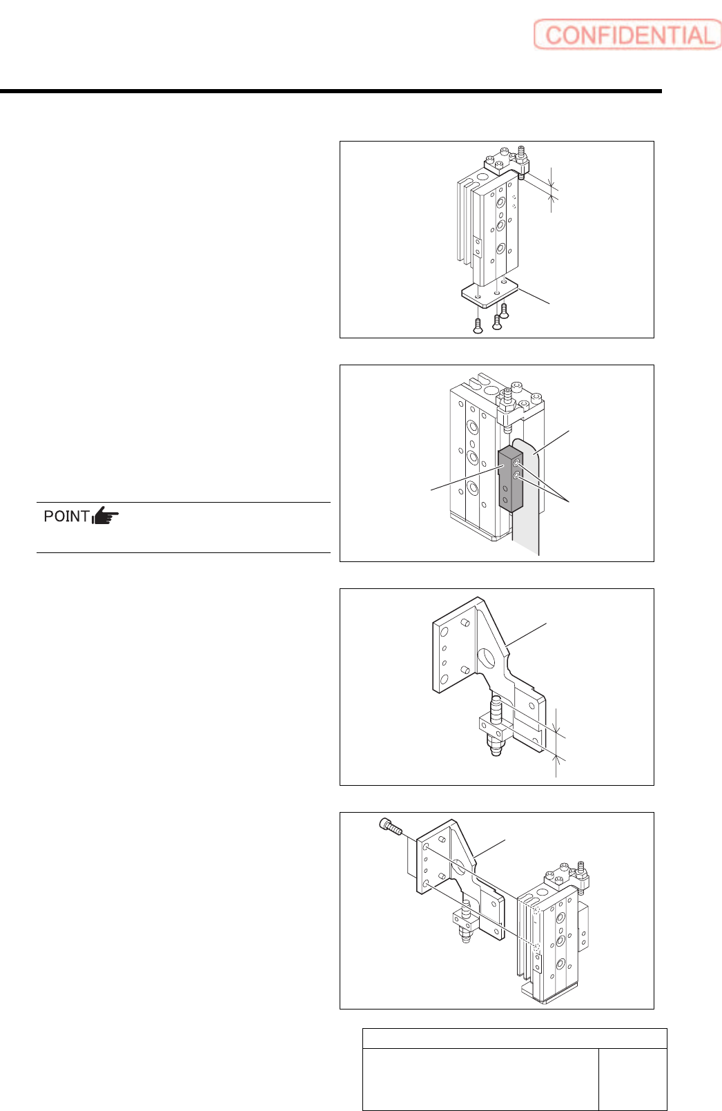
[Reassembling Procedure]
1 Secure the cylinder cover with 3-+K3x6.
2 Make sure the protrusion of the adjuster
from the backward end is 4 [mm].
3 Apply small amount of LOCTITE 242 to
2-CP2x6 and attach the stopper block.
Fix the stopper block so that clearance between the
side of the stopper block and the cylinder becomes
1.0mm.
Tightening torque: 54[cNm]
4 Adjust the protrusion of the shock absorber
to 11 [mm].
5 Apply small amount of LOCTITE 242 to
2-CP4x6 and attach the main bracket.
Cylinder cover
4.0 mm
Stopper block
Thickness gauge
(1.0mm)
2-CP2x6
11.0 mm
Main bracket
Main bracket
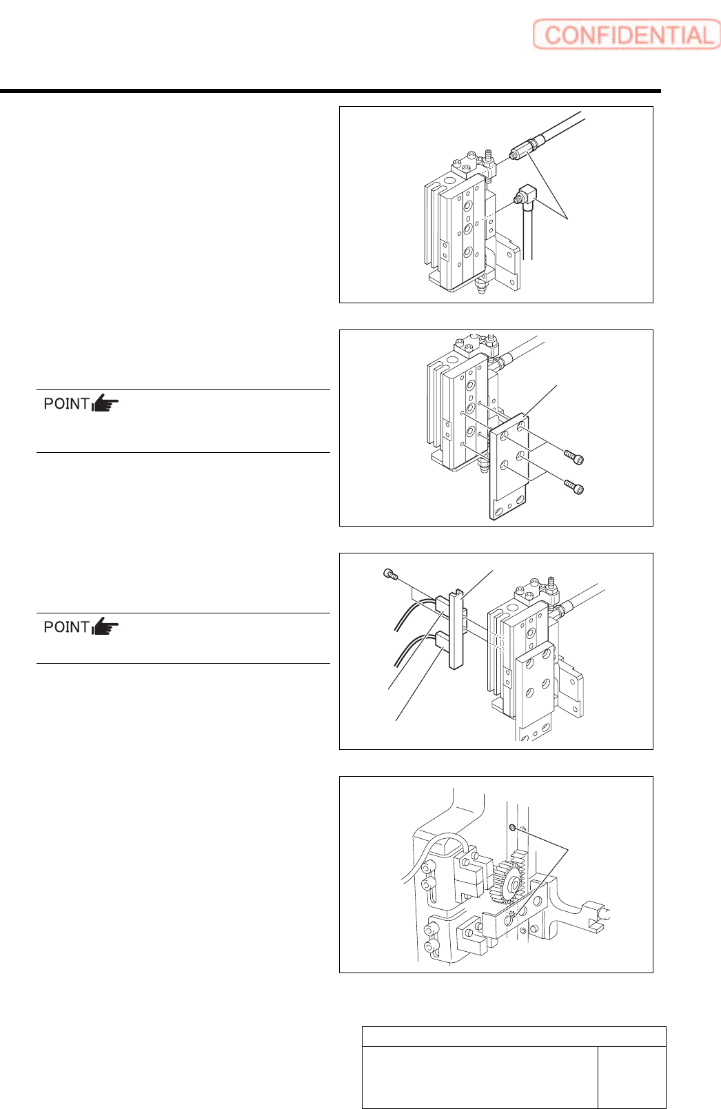
Pickup Check Camera Part
RPGB-10201-01
Pickup Check Camera Up/Down
Cylinder Replacement
SHEET
5/7
6 Connect the pipe fitting.
7 Apply small amount of LOCTITE 242 to
4-CP3x6 and secure the camera holder.
Apply AFC grease thinly to the pin press-fitted
in the camera holder.
8 Attach the cylinder sensor holder and the
cylinder sensor with 2-CP3x5.
SSB-4 comes top and SSB-2 comes bottom.
9 Attach the pickup check Up/Down unit of
Pick up check camera with 2-CP4x6 from
rear side of the head.
Pipe fitting
Camera holder
Cylinder sensor holder
SSB-4
SSB-2
2-CP4x6
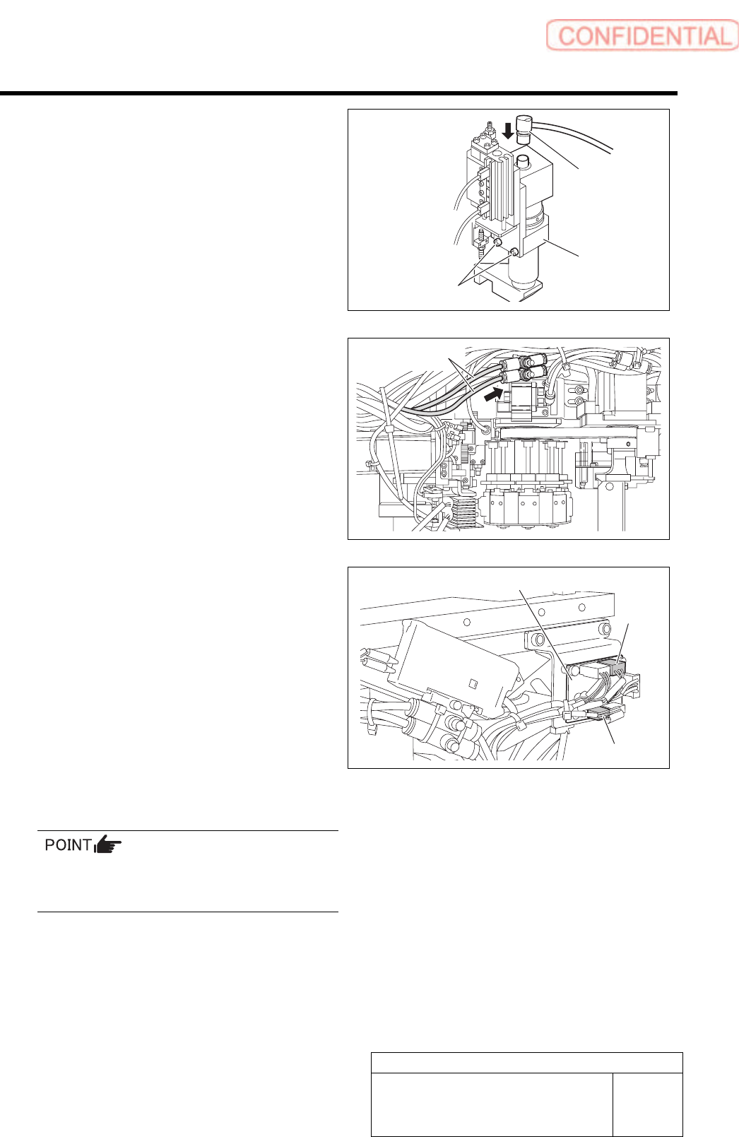
Pickup Check Camera Part
RPGB-10201-01
Pickup Check Camera Up/Down
Cylinder Replacement
SHEET
6/7
10 Secure the pickup check camera with
2-CP4x8 and connect the CAM2-UF camera
cable connector.
11 Connect the air tubes to the speed controller
on the rear side of the head. After
connecting the air tubes, bundle them
together using the cable tie (Insulock).
12 Connect SSD-2 and SSB-4 to the SSB
board on the side of the head, and then
fasten the cables with the cable tie
(Insulock).
13 Install the F-axis to the head.
For the F-axis unit removal procedure, refer to
“F-Axis Belt Replacement Procedure
[RPGB-10101-01]”.
14 Connect the air and turn on the system
power.
CAM2-UF
Pickup check
camera
Air tubes
SSB board
SSB-2
SSB-4
2-CP4x8