MAN00000772_SI-G200BB_SVCPDFA.pdf - 第347页
Adjustment HLGB-10419-01 Fixed Camera Pickup Ch eck Sensor Adj ust ment SHEET 2/7 3 Fix the fixed camera jig base with cap screws (2-CP 5x20). Carry out working with care not to damage the fiber cable for parts presence/…
Adjustment
HLGB-10419-01
Fixed Camera Pickup Check Sensor
Adjustment
SHEET
1/7
Fixed Camera Pickup Check Sensor Adjustment
Perform this operation for fixed camera pickup check sensors on both of front and rear sides.
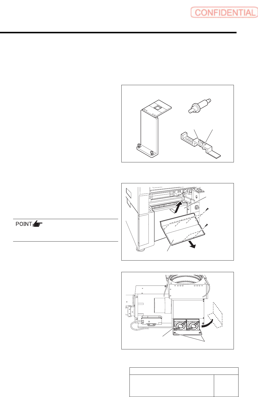
[Necessary jigs]
A Fixed camera Jig base (G200)
B Nozzle Jig for fixed camera
C Fixed camera parts presence/absence
sensor adjustment Jig
D Sensor adjusting nozzle (1)/long thin
E Sensor adjusting nozzle (2)/short thick
[Procedure]
1 Remove the lower cover and shooter on the
front and rear of the unit.
1. Loosen screw (2-+T4x8) to remove the
lower cover.
Tile the lower cover slightly toward you and pull
the fan cable to remove the lower panel.
2. Loosen screw (2-+T4x8) to remove the
shooter.
2 Loosen cap screws (2-CP5x10) fixing the
fixed camera cooling fan to remove the fan.
Temporarily place the removed fan on the side of the
fixed camera.
B
A
C
D E
Lower cover
Shooter
Cap screw
Cooling fan
Adjustment
HLGB-10419-01
Fixed Camera Pickup Check Sensor
Adjustment
SHEET
2/7
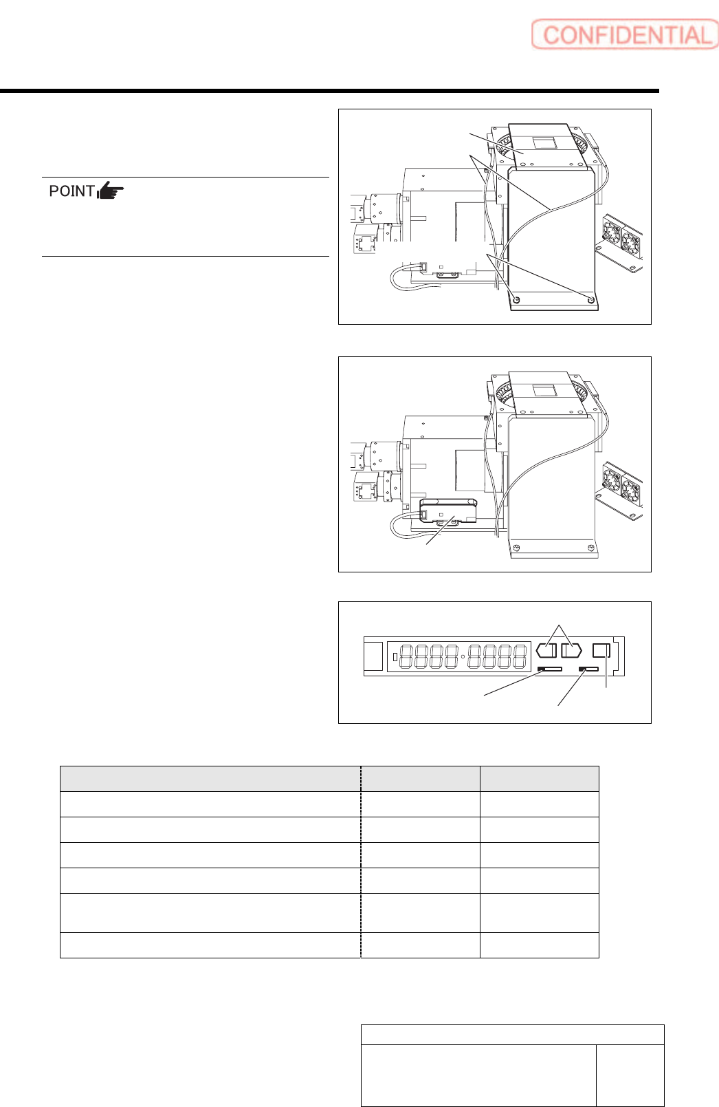
3 Fix the fixed camera jig base with cap
screws (2-CP5x20).
Carry out working with care not to damage the
fiber cable for parts presence/absence detecting
sensor.
4 Check setup of the sensor amplifier.
1. Open the cover for the sensor
amplifier.
2. Turn the SET/RUN selector switch to
SET.
3. Press the MODE button to select item
to be set.
4. Press the UP/DOWN button to change
the set button.
SET RUN
L D
Item to be set Indication Set value
Detecting function setup (Standard function)
1-Fn Stnd
Timer function (Not used)
2-bF ----
MODE setup(Power tuning execution)
3-Ad PtUn
Power tuning target value setup
PL 2000
Indication switching(light receiving quantity,
threshold are indicated)
2134 1000
Indicating direction setup
5-ru d123
Fixed camera jig base
Fiber cable
Cap screw
SET/RUN selector switch
Operation mode selector switch
MODE button
UP/DOWN button
Sensor amplifier
Adjustment
HLGB-10419-01
Fixed Camera Pickup Check Sensor
Adjustment
SHEET
3/7
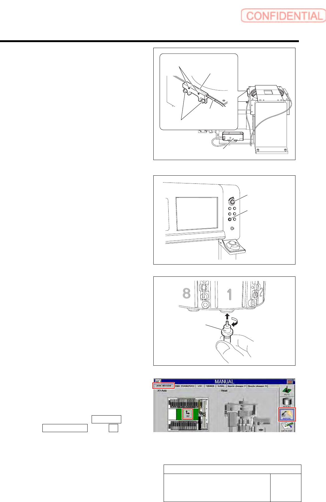
5 Check that the displayed value on the
sensor amplifier is “3800” or more.
1. Check that the displayed value on the
sensor amplifier is “3800” or more.
When the displayed value is less than “3800”,
adjust the sensitivity according to the following
procedures 2. and 3.
2. Loosen the sensor bracket mounting
bolt, and move the sensor bracket up
and down, to left and right to adjust
the fiber sensor mounting position.
3. Loosen the set screw to adjust rotating
direction of the pickup check sensor.
6 Release the emergency stop switch to
return the unit to the origin.
1. Turn the emergency stop switch to
release emergency stop.
2. Click the [ORG] button to return the
system to the original position.
7 Move the head to a position where working
can be easily performed and install the jig
nozzle for fixed camera to the turret No.1.
8 Move the center of the fixed camera jig
nozzle to cross point of the hair lines on the
XY Axis screen by manual operation.
1. Click in an order of MANUAL menu
AXIS MOTION tab XY button.
XY Axis screen is displayed.
Nozzle Jig for
fixed camera
Set screw
Sensor amplifier
Mounting bolt
Sensor
bracket
Fiber sensor
Emergency stop
switch
ORG button