MAN00000772_SI-G200BB_SVCPDFA.pdf - 第221页
Calibration HLGB-10305-01 Auto Calibration (Recognition of Relationship be t ween the Fi xed Camera and Nozzle) SHEET 4/4 8 Check that it was nor mally ende d, and click the Save button. Calibration result is saved. If a…
Calibration
HLGB-10305-01
Auto Calibration (Recognition of
Relationship between the Fixed Camera
and Nozzle)
SHEET
3/4
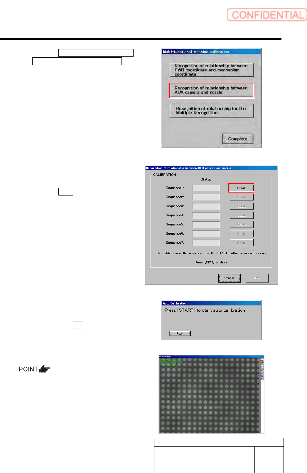
2. Click the Recognition of relationship
between AUX camera and nozzle
button on the Multi-functional
machine calibration screen.
Recognition of relationship between AUX
camera and nozzle screen is displayed.
7 Start calibration for relationship between the
fixed camera and nozzle.
1. Click the Start button of Sequence 1.
2. Press the [START] button to start the
auto calibration.
Sequence after the Start button is clicked is
subsequently executed.
In a process of recognizing a large glass PWB,
some portion of PWB may not be recognized.
Even so, keep on the operation.
Calibration
HLGB-10305-01
Auto Calibration (Recognition of
Relationship between the Fixed Camera
and Nozzle)
SHEET
4/4
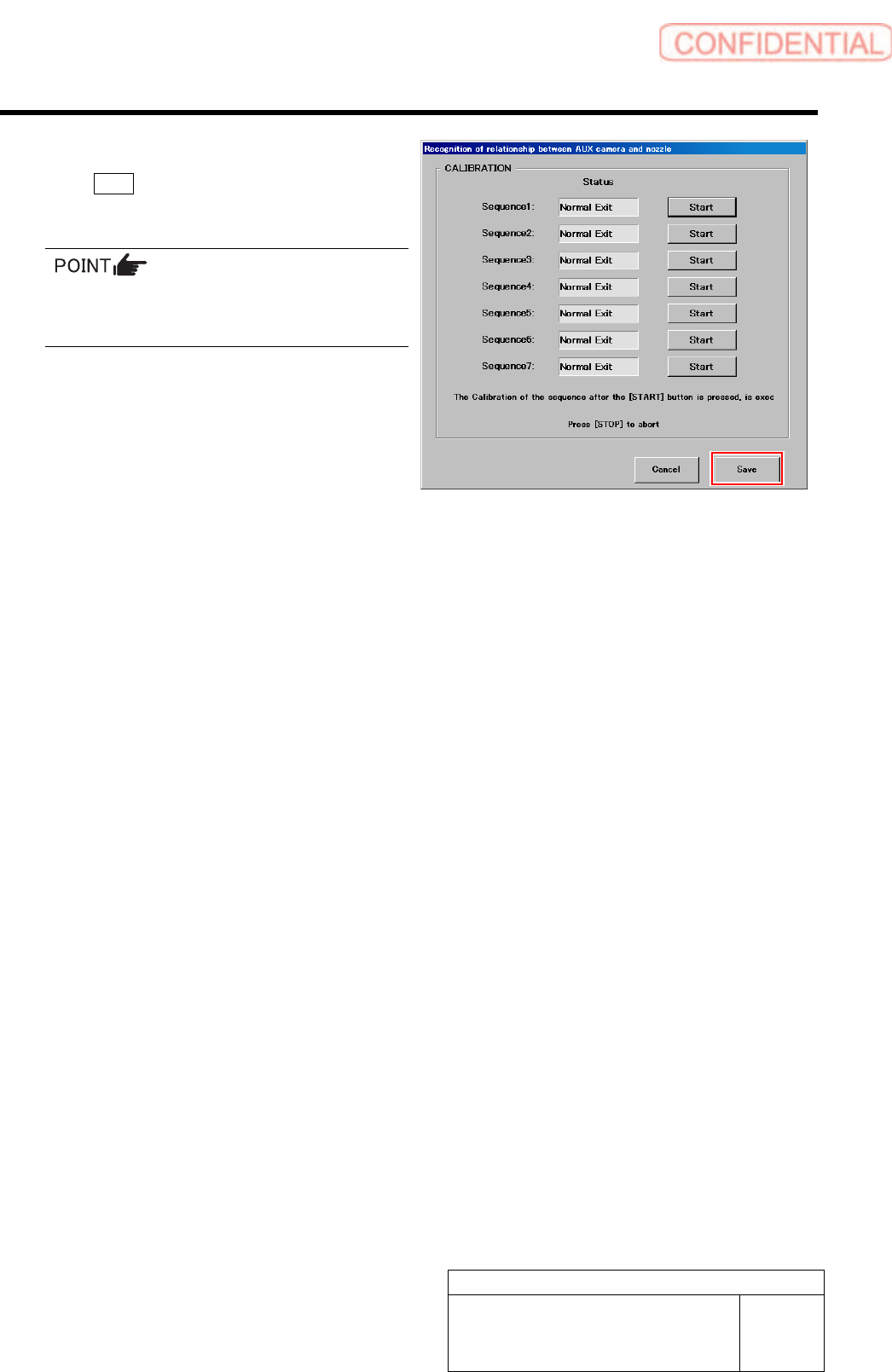
8 Check that it was normally ended, and click
the Save button.
Calibration result is saved.
If an error occurs and the process aborts, clean
the jig chips and then restart the calibration
from Sequence 1.
9 Go on to the procedure of recognition of relationship for the Multiple Recognition.
It is unnecessary to remove the jig because the same jig is used even in operation of relationship for the Multiple
Recognition.
・ For the Recognition of relationship for the Multiple Recognition procedure, refer to “Auto Calibration (Recognition of
Relationship for the Multiple Recognition) [HLGB-10306-01]”.
Calibration
HLGB-10306-01
Auto Calibration (Recognition of
Relationship for the Multiple Recognition)
SHEET
1/4
Auto Calibration (Recognition of Relationship for the Multiple
Recognition)
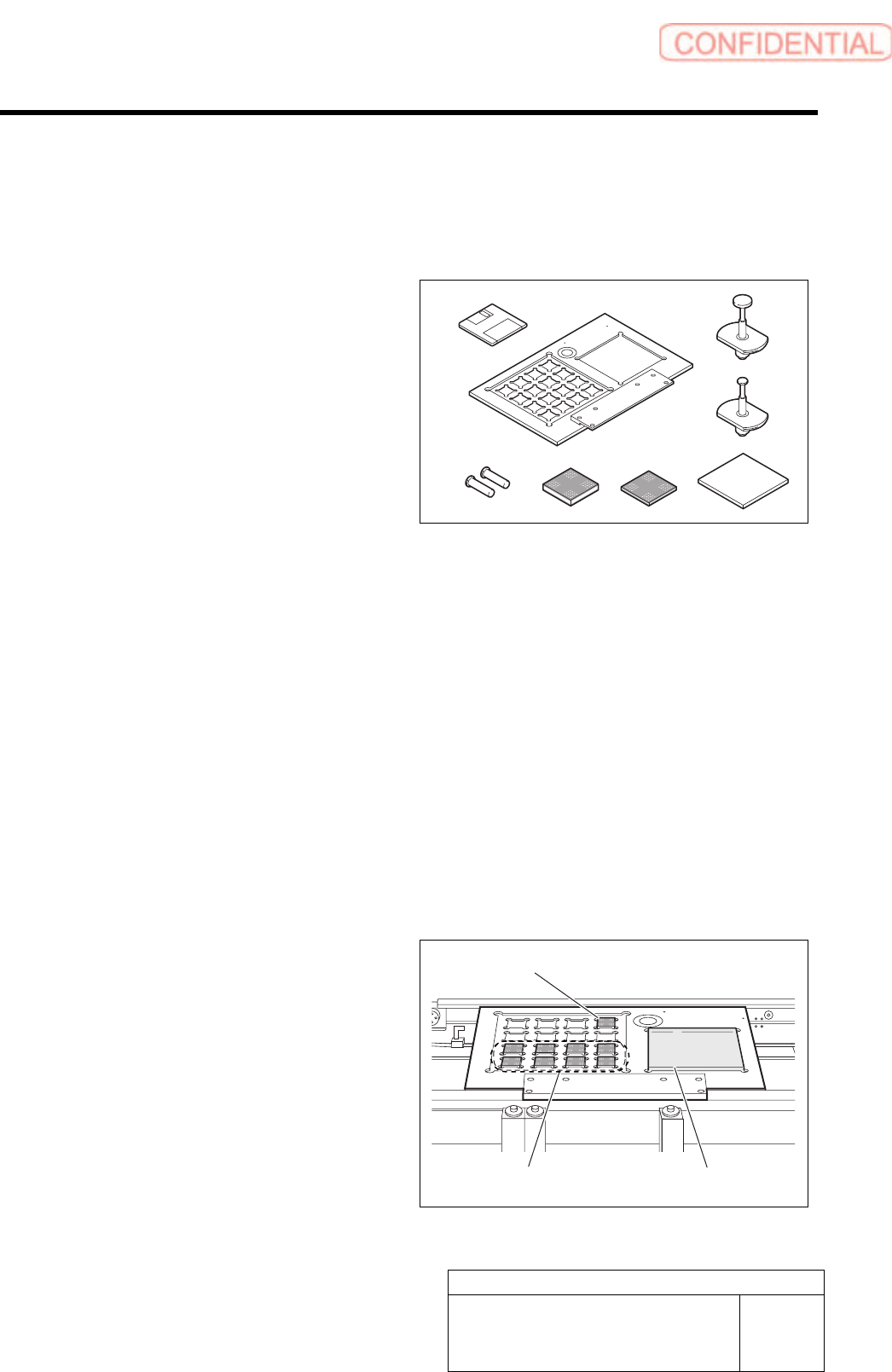
[Necessary jigs]
A Calibration data FD
B Calibration plate jig
C Positioning pins for calibration plate
D BF00900 nozzle (1 pc.)
E BF60400 nozzle (7 pcs.)
F Calibration jig chip (t=3.4, 1 pc.)
G Calibration jig chip (t=1.4, 8 pcs.)
H Calibration jig chip (glass)
[Procedure]
When performing recognition of relationship for the Multiple Recognition subsequently from
calibration of position relationship between the fixed camera and nozzle, start operation from the
procedure 6.
1 Load the calibration data.
For calibration data loading procedure, refer to “Calibration Data Load [HLGB-10105-01]”.
2 Install the calibration plate jig.
For mounting method of the calibration plate jig, refer to “Install the Calibration Plate Jig [HLGB-10101-01]”.
3 Put the jig tip on the calibration plate.
1. Put 8 thinner jig chips (t=1.4mm) to
front side.
2. Put thicker jig chip (t=3.4mm) to the
right end of the deep row.
3. Put jig chip (glass) on the right
countersunk section.
Set the jig chips so that surface on which glass
black point (pattern) is printed is directed
upward.
E
D
A
B
C
F
G H
Jig chip (t=3.4mm)
Jig chip (t=1.4mm) Jig chip (glass)