MAN00000772_SI-G200BB_SVCPDFA.pdf - 第350页
Adjustment HLGB-10419-01 Fixed Camera Pickup Ch eck Sensor Adj ust ment SHEET 5/7 10 Servo o ff only H-axis. 1. Click in an order of M/ C SETUP men u ORG OFFSET tab Indv . Axis button. Indv . Axis Servo screen is dis…
Adjustment
HLGB-10419-01
Fixed Camera Pickup Check Sensor
Adjustment
SHEET
4/7
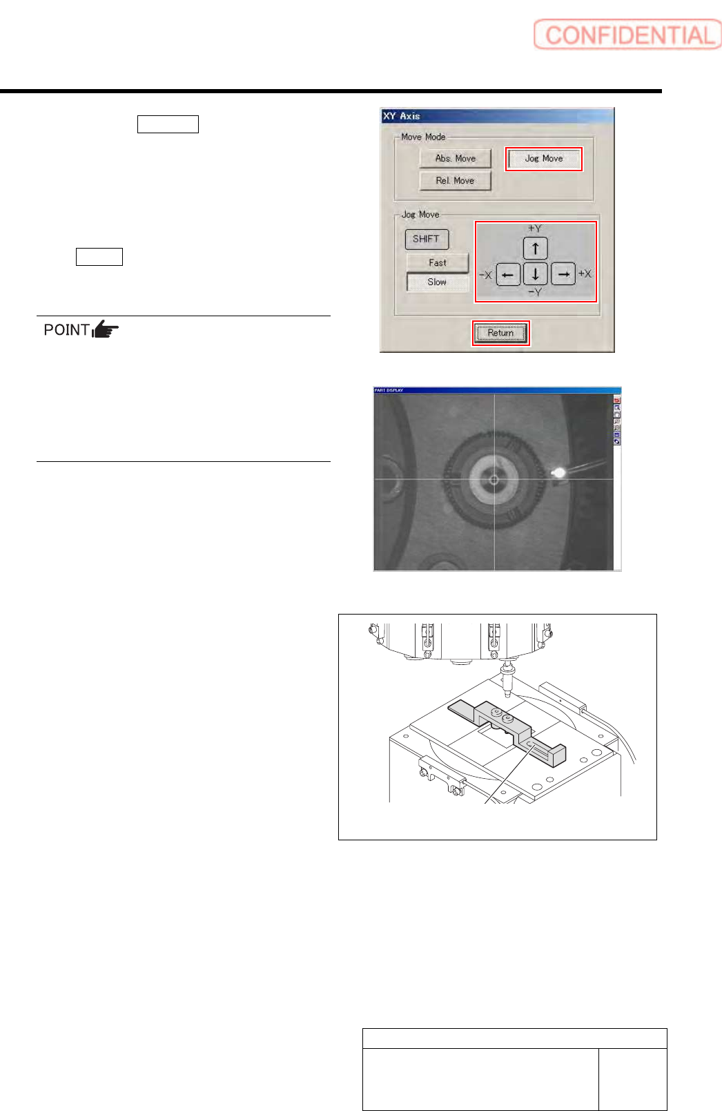
2. Click the Jog Move button.
3. Press the cursor key and move the
center of the fixed camera jig nozzle to
cross point of the hair lines on the
PARTS DISPLAY screen.
4. After moving the head, click the
Return button to close the XY Axis
screen.
When performing this operation immediately
after auto calibration, absolute-move the head to
the position described
on#PbPointForFixedCam1 in Calibration.dat
using MANUAL/AXIS MOTION menu to adjust
fine position. More accurate position adjustment
will be possible.
9 Put “Fixed camera parts presence/absence
sensor adjustment jig“ on “Fixed camera
jig base“.
Fixed camera parts presence/absence
sensor adjustment Jig
Adjustment
HLGB-10419-01
Fixed Camera Pickup Check Sensor
Adjustment
SHEET
5/7
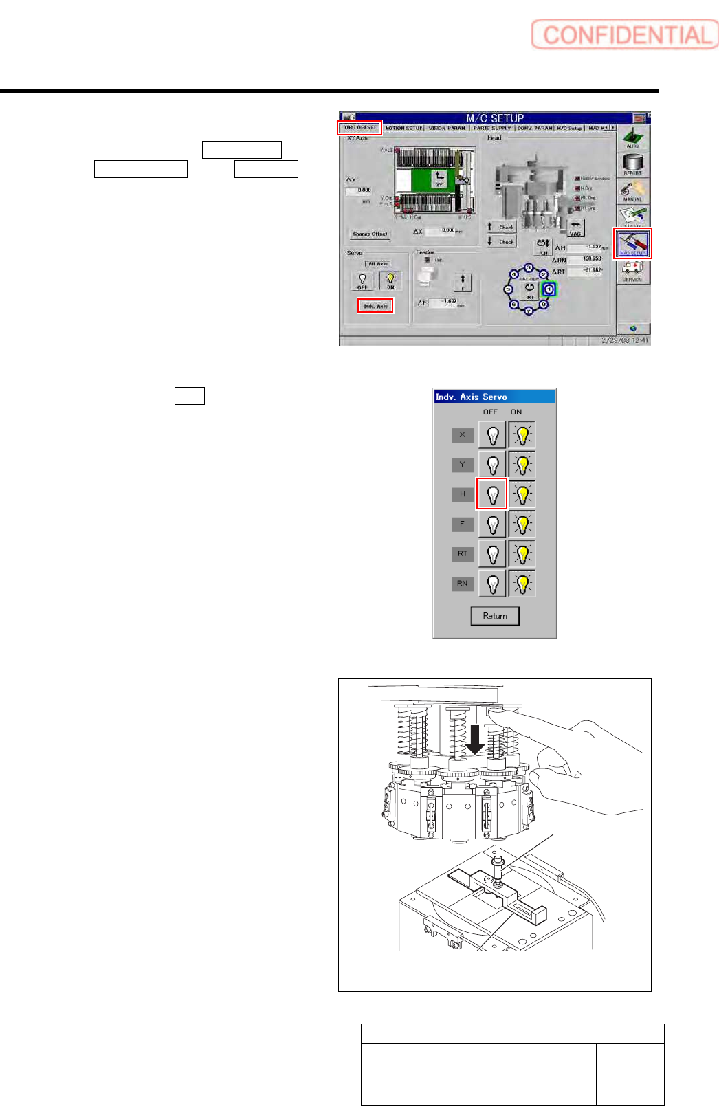
10 Servo off only H-axis.
1. Click in an order of M/C SETUP menu
ORG OFFSET tab Indv. Axis
button.
Indv. Axis Servo screen is displayed.
2. Click the servo OFF button for H axis.
Servo for H axis is turned off.
11 Check whether “Sensor adjusting nozzle
(1) “ is under the “Jig nozzle for fixed
camera“. Fix “Fixed camera parts
presence/absence sensor adjustment
jig“ After check the position of “Sensor
adjusting nozzle (1) “.
Fixed camera parts presence/absence
sensor adjustment Jig
Nozzle Jig for
fixed camera
Adjustment
HLGB-10419-01
Fixed Camera Pickup Check Sensor
Adjustment
SHEET
6/7
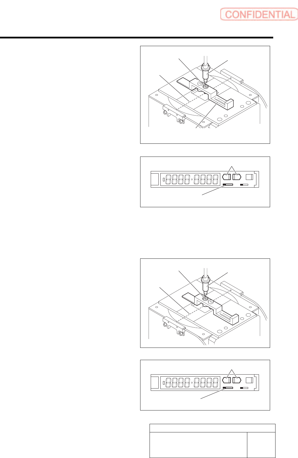
12 Move the sensor adjusting nozzle (1) to right
under the jig nozzle for fixed camera.
13 Put the sensor adjusting nozzle (1) at a
position where optical axis of the sensor is
shielded.
14 Set threshold of the sensor.
1. Turn the SET/RUN selector switch to
SET side.
2. Check that the sensor adjusting nozzle
(1) is just below the fixed camera jig
nozzle.
3. Press either one of DOWN or UP
button.
Light receiving quantity when shielded is
displayed, and then it returns to the indication
before operation.
SET RUN
L D
4. Move the sensor adjusting nozzle (2)
just down to the fixed camera jig
nozzle.
5. Press either one of DOWN or UP
button.
Light receiving quantity when shielded is
displayed, and then it returns to the indication
before operation.
6. Turn the SET/RUN selector switch to
RUN side.
SET RUN
L D
Sensor adjusting
nozzle (1)
Nozzle Jig for
fixed camera
SET/RUN select or switch
Fixed camera parts presence/absence
sensor adjustment Jig
UP/DOWN button
Optical axis
Sensor adjusting
nozzle (2)
Nozzle Jig for
fixed camera
Optical axis
SET/RUN selector switch
UP/DOWN button