MAN00000772_SI-G200BB_SVCPDFA.pdf - 第672页
Ch ange Procedu re for RT Axi s Moto r U n i t Change Pro cedure fo r RT A x is M otor Unit [Necess a r y Jigs] Te nsion Mete r(UNITT A U-507) Be lt Tensio n JIG (B ) [Disassembly] 1 Open the f ront and re ar slide do o …
Change Procedure for RN Axis Motor Unit
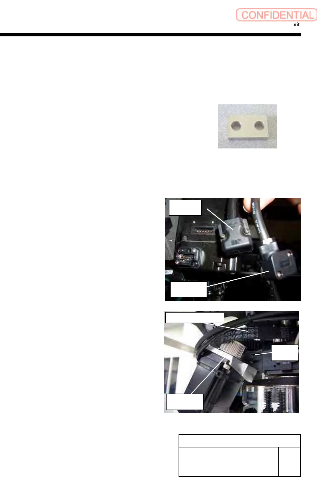
10 Attach the motor.
1. Apply the RN timing belt to the pulley on the motor.
2. Lock the new motor to the bracket by temporarily
Fastening screws C5x20, C5x12 and 2-W5.
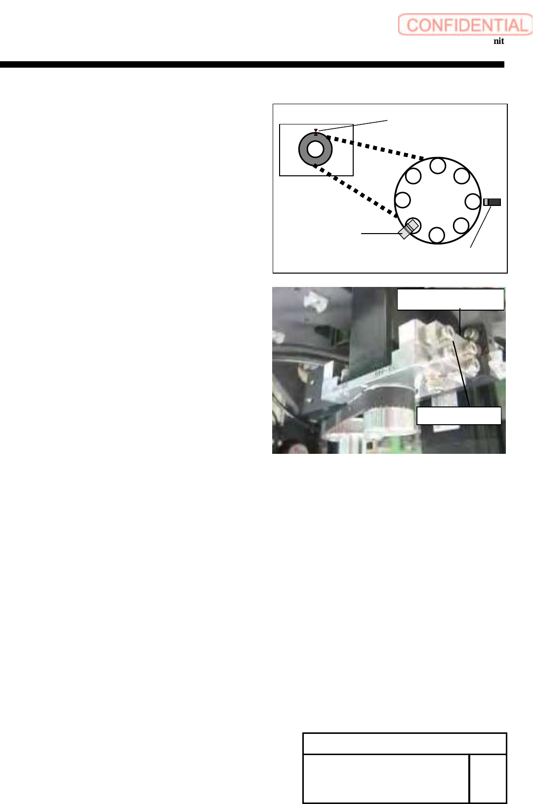
3. Observe the rule of the following position at the installation.
Position of RN dog and number 6 shaft.
Position of H axis lever and number 1 shaft.
Z phase of RN motor.
11
Attach the Tension JIG to the Motor bracket.
Move the Motor Holder to the position in which the tension
of the RN-axis timing belt gains by adjustment screw.
measure the tension with the Tension Meter, and lock the
bracket in the position in which the tension becomes
44±5N. (4 point measure)
UNITTA U-507
Weight 2.5gf/m
Width 9mm
Span 96mm
12 Detach Tension JIG when the adjustment ends.
13 Lock the wiring with the cable tie not allow the
Wiring to interfere with the movable parts.
[Adjustment]
14 Calibration
1. HLGB-10207-01 RN AXIS Origin Offset
2. HLGB-10414-01 Nozzle Phase Adjustment
3. HLGB-10304-01 Calibration
Change Procedure for RN-axis
Motor Unit
RPGB-10501-1
SEET
3/3
8
7
6
5
4
3
2
1
H axis lever
RN dog
Motor Z phase
Belt Tension Jig
Adjustment screw
Change Procedure for RT Axis Motor Unit
Change Procedure for RT Axis Motor Unit
[Necessary Jigs]
Tension Meter(UNITTA U-507)
Belt Tension JIG (B)
[Disassembly]
1 Open the front and rear slide doors of the main body.
2
Push the head base to the center.
3 Cut the cable tie locking the wiring of the motor.
4 Remove the power cable and the encoder cable.
5 Remove the screws (4-C4x18), and detach
the bracket.
Change Procedure for RT-axis
Motor
Unit
RPGB-10601-1
SEET
1/4
Encoder
cable
Power
cable
RT Axis Motor
Bracket
C
4
x
18
W4
RT Axis Timing Belt
Change Procedure for RT Axis Motor Unit
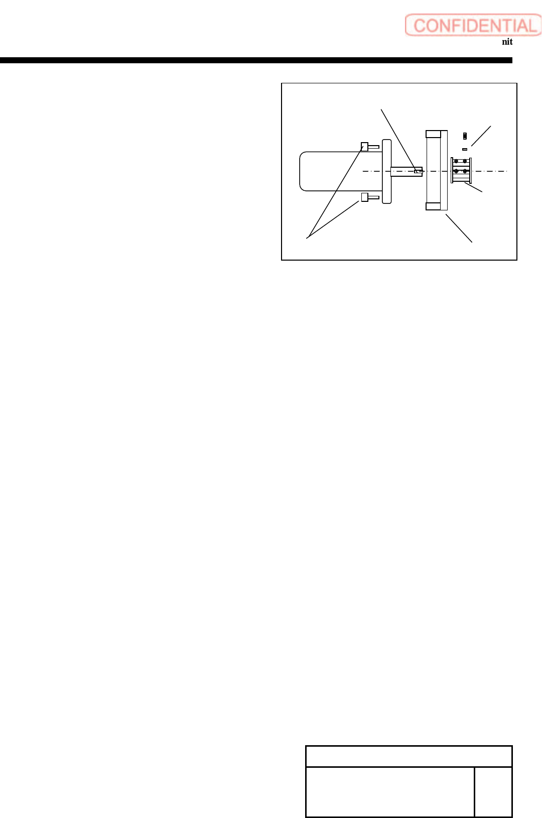
6 Remove the screws (4-C5x12) and motor bracket.
7
Remove the screws (2-H2.5x4, 2-H3x5), set shoe (2)
and pulley.
CAUTION
There is a set shoe behind the screw which
locks the pulley in the keyless position.
Remove the set shoe, and safekeep it not to lose it.
Motor Bracket
Pulley
C5x12
H3
x
5
Set Shoe
H2.5x4
Key
Change Procedure for RT-axis
Motor Unit
RPGB-10601-1
SEET
2/4