MAN00000772_SI-G200BB_SVCPDFA.pdf - 第639页
在线预览 MAN00000772_SI-G200BB_SVCPDFA.pdf PDF 文档。

CLGB-0004-01
SI-G200BB Service manual
“Parts Replacing Manual Contents”
SHEET
1/1
Contents
10 F, XY axis movable part, Pickup Check Camera Part, Head part
F Axis Belt Replacement Procedure ......................................RPGB-10101-01
Pickup Check Camera Up/Down Cylinder Replacement .......RPGB-10201-01
Pickup Check Light Up/Down Cylinder Replacement ............RPGB-10202-01
Change Procedure for Head Unit...........................................RPGB-10301-01
Change Procedure for PWB Camera.....................................RPGB-10401-01
Change Procedure for RN Axis Motor Unit ............................RPGB-10501-01
Change Procedure for RT Axis Motor Unit ............................RPGB-10601-01
Change Procedure for Rotary Encoder..................................RPGB-10701-01
Change Procedure for RN Axis Timing Belt...........................RPGB-10801-01
Change Procedure for RT Axis Timing Belt ...........................RPGB-10901-01
Change Procedure for H Axis Motor Unit...............................RPGB-11001-01
Change Procedure for Lever Assembly of Head Unit ............ RPGB-11101-01
Change Procedure for X Axis LM-guide.................................RPGB-11201-01
Change Procedure for Y Axis LM-guide.................................RPGB-11301-01

F axis movable part
RPGB-10101-01
F Axis Belt Replacement Procedure
SHEET
1/9
F Axis Belt Replacement Procedure
[Necessary Jigs]
• Tension meter (UNITTA U-505)
• Tension jig (for G only)
[Removal]
1 Open the slide door on the front side of the main body or the slide door on the rear side of the main
body.
2 Press the head base to move it to the area in which it is easy to work with.
3 Sever the Insulock that ties the wiring down.
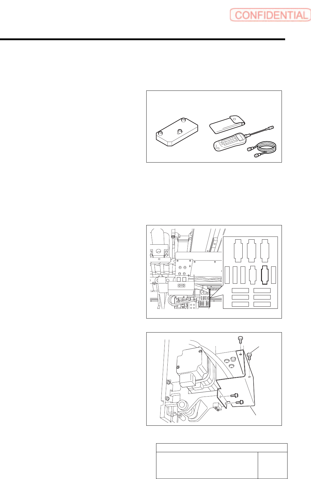
4 Remove the FSEN2F connector from the
relay plate.
RNFM
RTFM
HFM
FSEN2F
LEDF
RTFE
RNFE
PDF
BLKF
CSFT-LSF
CSF TF
HFE
RTSF
RNSF
VACF-2
5 Unscrew 4-C3x6 screws to remove the
cover.
Tension jig Tension meter
Cover
4-C3x6