MAN00000772_SI-G200BB_SVCPDFA.pdf - 第706页
XY axis movable parts RPGB-1 1301-01 Change Procedure for Y Axis LM-GUIDE SEET 4 / 9 5, JIG moves to the next position Please repeat 3.4 works 6, Confirm the gap between base level and LM-guide POINT Thickness gauge0.01m…
XY axis movable parts
RPGB-11301-01
Change Procedure for
Y Axis
LM-GUIDE
SEET
3/9
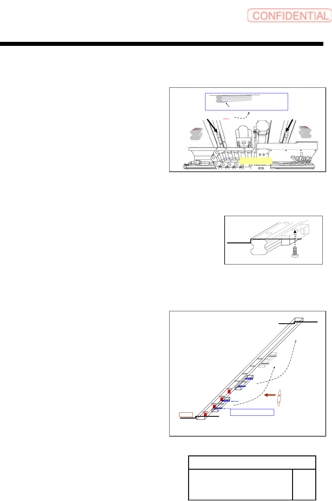
2, Install LM-guide and temporarily stop the screw
POINT
From M/C FRONT view
Left sides LM-guide have KB mark
Right side LM-guide have not KB mark
(KB mark is written in the end of serial No)
Be careful base line arranges install to the outside
(Base line in the installation side)
Working operation is from FRONT side go to REAR side
3, Set LM-guide hold jig on the install position,
Tighten it by M6
POINT
Presses side is seen at back.
Position order start is from left-hand side
І , П , (Ш···)
4, Tighten of tension screw (M4) for
press to L M-guide and base
After tighten of LM-guide fixed screw
M4 tension screw Tightening torque 50 (cN.m)
LM-guide screw Tightening torque 588(cN.m)
POINT
Presses side is seen at back.
Position order start is from left-hand side
1,2,3,(4···)
JIG
〈FRONT View〉
Serial No,○○○・・・
KB
Serial No,○○○・・・
base line
base line
SERIAL No, (the end of a KB mark)
1
2
3
4
・
・
・
Ⅰ
Ⅱ
Ⅲ
M4 Tension screw
Left side
XY axis movable parts
RPGB-11301-01
Change Procedure for
Y Axis
LM-GUIDE
SEET
4/9
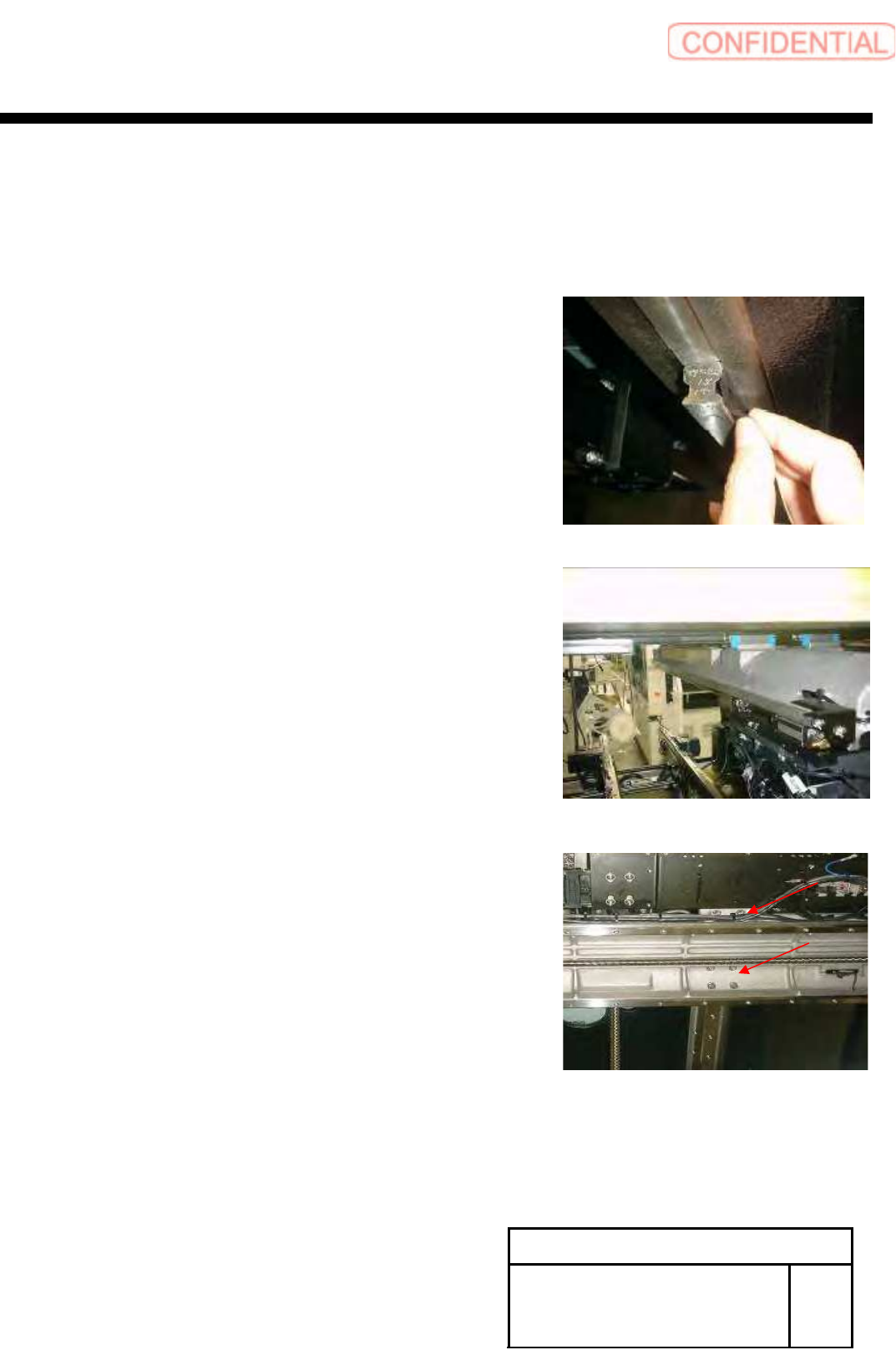
5, JIG moves to the next position
Please repeat 3.4 works
6, Confirm the gap between base level and LM-guide
POINT
Thickness gauge0.01mm do not enter
7, Cleaning of the slide block and installation surface
8, Match a slide block with the installation side of the X-axis,
Temporarily stop the screw (LM-guide of right and left)
If the exchange work of one LM guide is finished as above, change other LM guide equally.
XY axis movable parts
RPGB-11301-01
Change Procedure for
Y Axis
LM-GUIDE
SEET
5/9
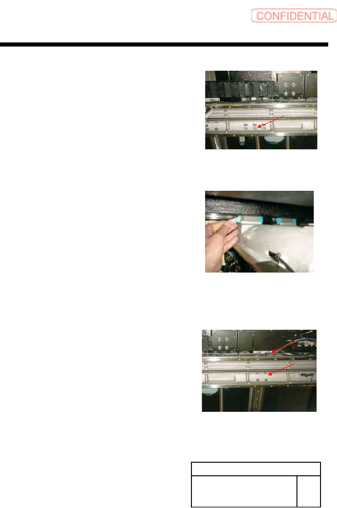
9, Fixed the screw in X-axis and nut holder of
a Y-axis ball screw, loosen it
POINT
Loosen it so that a ball screw does not have tension
10, Press to slide block and installation surface of the X-axis
Then tighten it (Left side LM-guide)
Confirm the gap between base level and LM-guide
POINT
Thickness gauge0.02mm do not enter
11, Slide block and installation surface of the X-axis tighten it
(Right side LM-guide)
POINT
Confirm Motion smoothly when move
Y-axis back and forth