MAN00000772_SI-G200BB_SVCPDFA.pdf - 第357页
Adjustment HLGB-10421-01 Ejector Setup SHEET 2/2 4 Adjust position of the CW sensor . 1. Move the pusher to the right side mechanical end by hand. 2. Shift the pusher by appr oximately 1mm in left dir ection from the mec…
Adjustment
HLGB-10421-01
Ejector Setup
SHEET
1/2
Ejector Setup
[Procedure]
1 Press the [ORG] button on the operation
panel to perform origin position return.
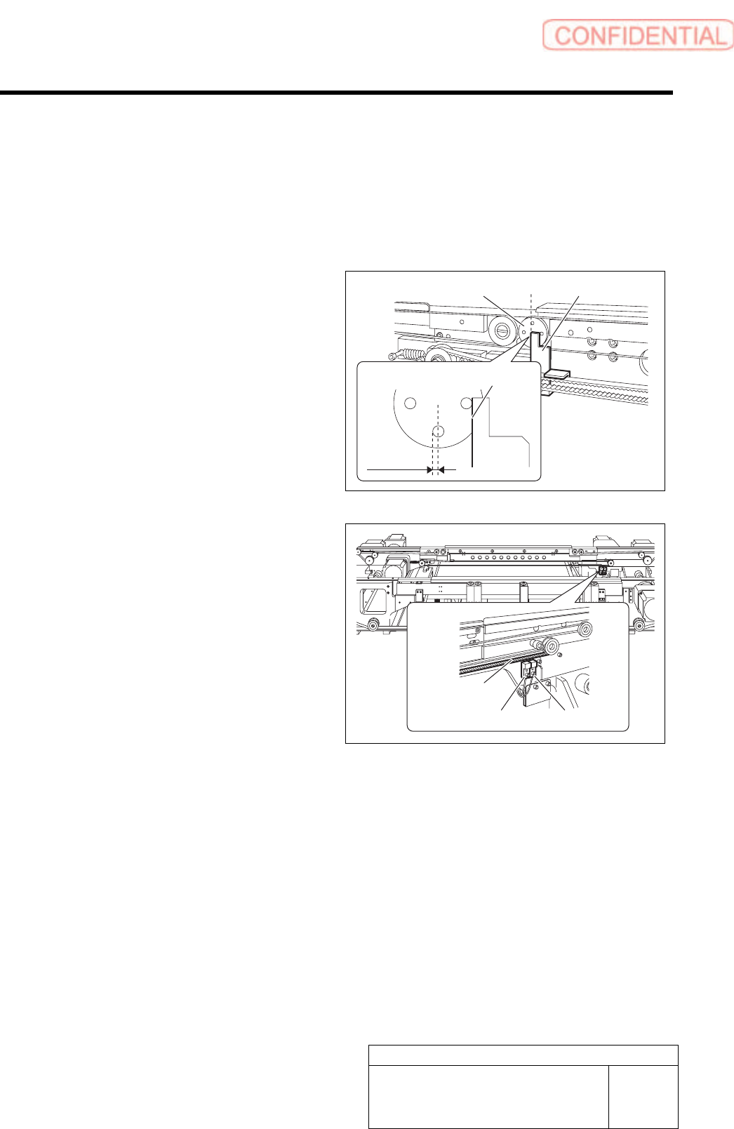
2 Adjust the pusher to the ORG sensor
position.
1. Set four holes on the left side pulley
horizontally/vertically.
2. Move the pusher by hand so that the
pusher left face is at the ORG position.
3. Loosen the screws on the mounting
bracket for the ORG sensor.
4. Tighten the screws on the mounting
bracket to fix on a boundary where the
LED on the ORG sensor changes to
lighting off to lighting up.
3 Move the pusher further in left direction, and
check that the LED on the CCW sensor
lights off before the pusher contacts the
mechanical end.
If the pusher contacts the mechanical end before the
LED on the CCW sensor lights off, adjust the position
of the ORG sensor.
Ejector belt
ORG sensor OT sensor
Pusher left face
ORG
position
Pusher Left side pulley
Adjustment
HLGB-10421-01
Ejector Setup
SHEET
2/2
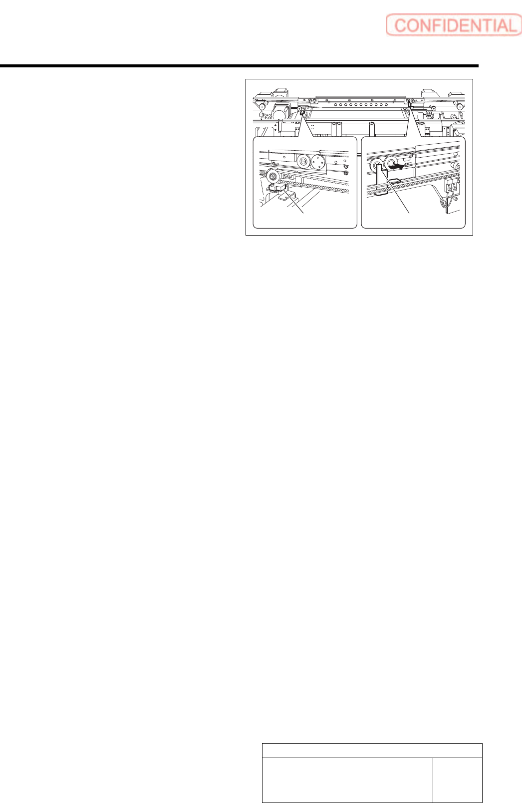
4 Adjust position of the CW sensor.
1. Move the pusher to the right side
mechanical end by hand.
2. Shift the pusher by approximately
1mm in left direction from the
mechanical end.
3. Loosen the screws on the mounting
bracket for the CE-CW sensor.
4. Fix the sensor mounting bracket on a
boundary where the LED on the
CE-CW sensor changes from lighting
off to lighting up.
CW sensor
Pusher
Adjustment
HLGB-10422-02
Blow Flow rate Setup
SHEET
1/4
Blow Flow rate Setup
This section describes a procedure to set up blow flow rate. Perform this working on both heads on
the front side and rear side.
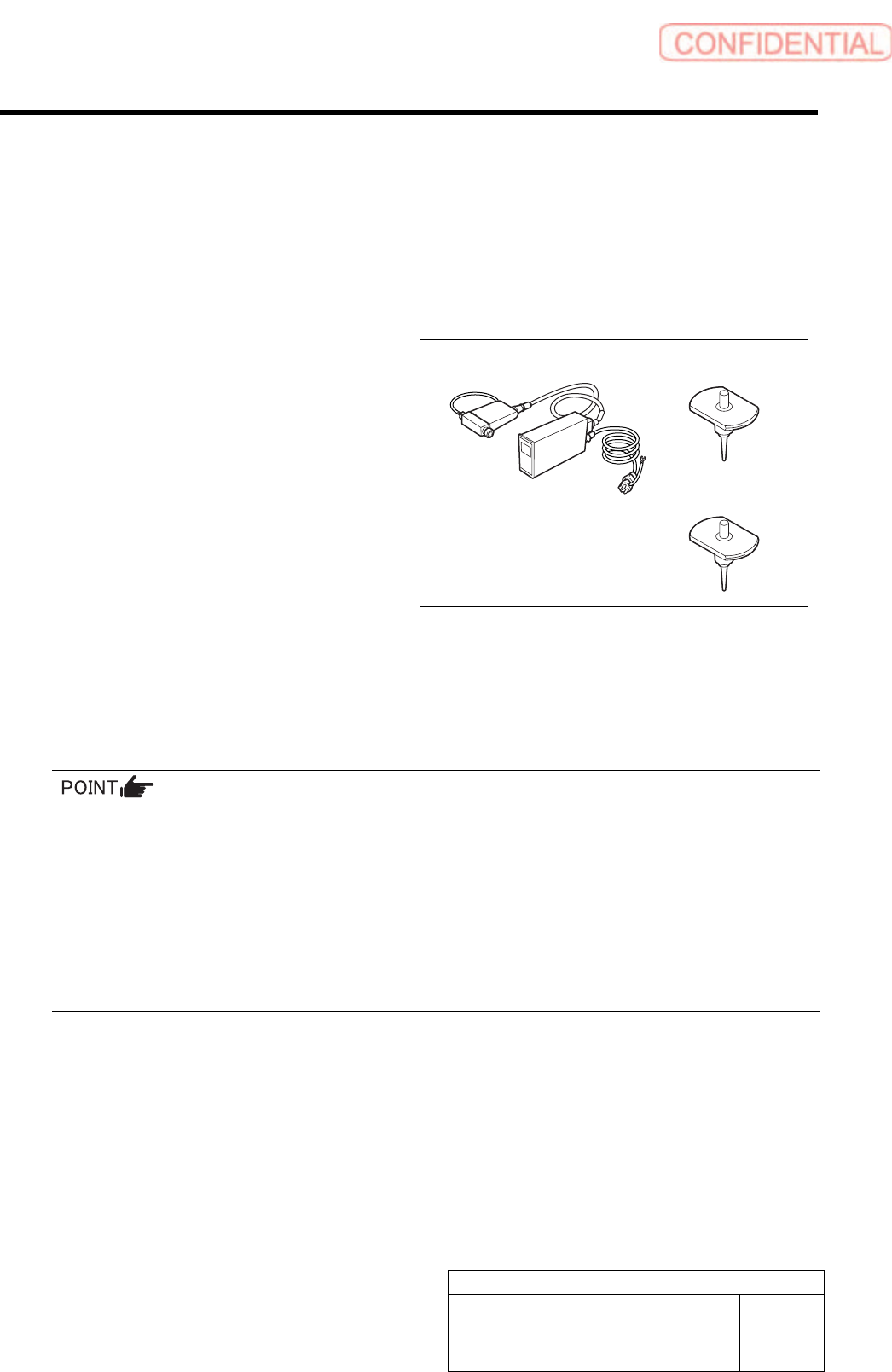
[Necessary jigs]
• Flowmeter
• Flow rate measuring nozzle Jig
(BF1305R)
• Nozzle jig (BF14100): 7 pieces
[Procedure]
1 Prepare flowmeter.
1. Turn on power for the flowmeter and warm up for one minute.
2. Check that the displayed value on the flowmeter is “0±0.009”.
When the displayed value on the flowmeter is not “0±0.009”, adjust the zero point in the following
procedure.
1) Close the IN-OUT part on the flowmeter with tape to warm up for 30 minutes.
2) Carefully remove the serial number seal on the upper of the flowmeter main body until the volume is
seen.
3) Slowly turn the zero adjustment volume (remote from the signal connector) with precision screw driver
to adjust zero point.
4) After zero point adjustment, return the serial number seal to the previous state, and remove the tape
closing the IN-OUT part.
Flowmeter
Flow rate measuring
nozzle Jig
Nozzle jig