MAN00000772_SI-G200BB_SVCPDFA.pdf - 第256页
Calibration HLGB-10312-01 Checking Pickup Positio n SHEET 3/4 5 Put check mark on the “Mov e nozzle end to pickup position” and pres s the [ST ART] button on the operation pan el. The length reference nozzle jig moves to…
Calibration
HLGB-10312-01
Checking Pickup Position
SHEET
2/4
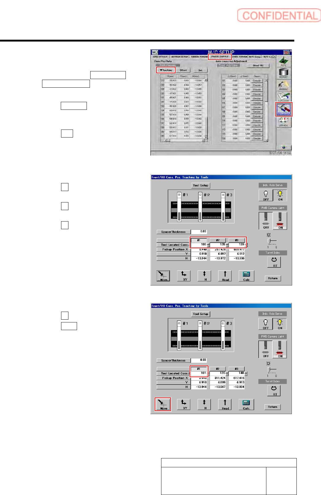
2 Display a Front/All Cass. Pos. Teaching by
Tools screen.
1. Click in an order of M/C SETUP menu
PARTS SUPPLY tab.
PARTS SUPPLY screen is displayed.
2. Click the Teaching button on the Front
Pos. Data to display a drop down
menu.
3. Click the Jigs in the drop down menu.
The Front/All Cass. Pos. Teaching by Tools
screen is displayed.
3 Set the tool located cassette No.
1. Click the #1 and input “101” in input
box for Tool Located Cass.
2. Click the #2 and enter “120” in the
input box for Tool Located Cass.
3. Click the #3 and input “140” in input
box for Tool Located Cass.
4 Display a Move screen.
1. Click the #1.
2. Click the Move button.
Move screen is displayed.
Calibration
HLGB-10312-01
Checking Pickup Position
SHEET
3/4
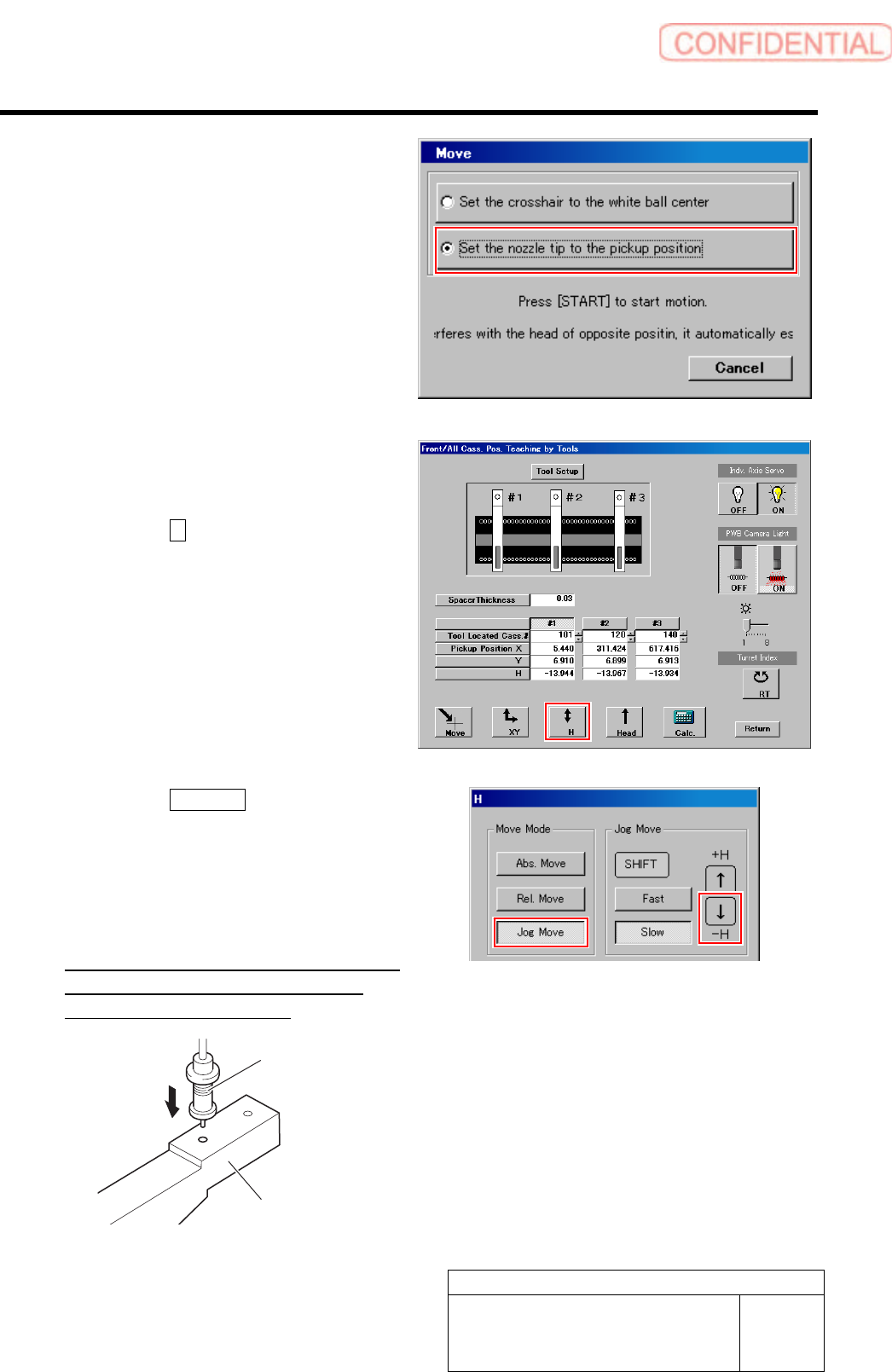
5 Put check mark on the “Move nozzle end to
pickup position” and press the [START]
button on the operation panel.
The length reference nozzle jig moves to above the
hole in front of the pickup point jig.
6 Check that end of the length reference
nozzle jig is smoothly inserted into the hole
in front of the pickup point jig.
1. Click the H button on the front and
cassette position whole teaching
screen.
H screen is displayed.
2. Click the Jog Move button.
3. Press the lower cursor key to check
end of the length reference nozzle jig is
smoothly inserted into the hole in
front of the pickup point jig.
If the end of the length reference nozzle jig is not
smoothly inserted, perform “Pickup position
setup” in the previous item again.
Pickup point Jig
Length reference
nozzle jig
Calibration
HLGB-10312-01
Checking Pickup Position
SHEET
4/4
7 Subsequently, check pickup position at positions of Z120、Z140.
1. Move the pickup point jig to the position of Z120 or Z140.
2. Click #2 or #3.
3. Click the Move button.
Move screen is displayed.
4. Check pickup position at the positions of Z120, Z140 by the same procedure as the
procedure 5-6.
If the end of the length reference nozzle jig is not smoothly inserted, perform “Pickup position setup” in the
previous item again.
8 When “Pickup position setup” and “Checking pickup position” on the front, also perform the “Pickup
position setup” and “Checking pickup position” on the rear in the same way.